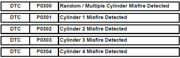
Toyota RAV4 (XA40) 2013-2018 Service Manual: Random / multiple cylinder misfire detected
Description
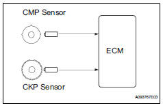
When the engine misfires, high concentrations of hydrocarbons (hc) enter the exhaust gas. Extremely high hc concentration levels can cause increases in exhaust emission levels. High concentrations of hc can also cause increases in the three-way catalytic converter (twc) temperature, which may cause damage to the twc. To prevent these increases in emissions and to limit the possibility of thermal damage, the ecm monitors the misfire rate. When the temperature of the twc reaches the point of thermal degradation, the ecm blinks the mil. To monitor misfires, the ecm uses both the camshaft position (cmp) sensor and the crankshaft position (ckp) sensor. The cmp sensor is used to identify any misfiring cylinders and the ckp sensor is used to measure variations in the crankshaft rotation speed.
Misfires are counted as when the crankshaft rotation speed variations exceed predetermined thresholds.
If the misfire rate exceeds the threshold level, and could cause emission deterioration, the ecm illuminates the mil and sets a dtc.
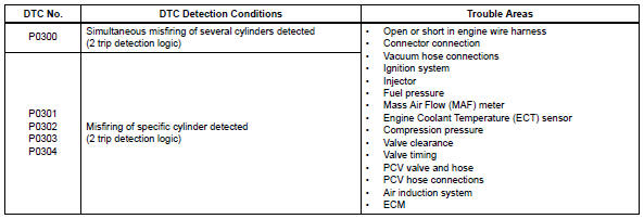
When dtcs for misfiring cylinders are randomly set, but dtc p0300 is not set, it indicates that misfires have been detected in different cylinders at different times. Dtc p0300 is only set when several misfiring cylinders are detected at the same time.
Monitor description
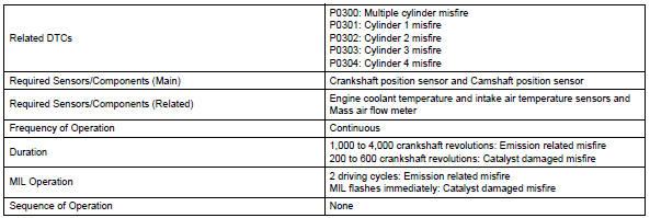
The ecm illuminates the mil and sets a dtc when either of the following conditions, which could cause emission deterioration, is detected (2 trip detection logic).
- Within the first 1,000 crankshaft revolutions of the engine starting, an excessive misfiring rate (approximately 20 to 50 misfires per 1,000 crankshaft revolutions) occurs once.
- After the first 1,000 crankshaft revolutions, an excessive misfiring rate (approximately 20 to 50 misfires per 1,000 crankshaft revolutions) occurs 4 times in sequential crankshaft revolutions.
The ecm flashes the mil and sets a dtc when either of the following conditions, which could cause three-way catalytic converter (twc) damage, is detected (2 trip detection logic).
- In every 200 crankshaft revolutions at a high engine rpm, the threshold misfiring percentage is recorded once.
- In every 200 crankshaft revolutions at a normal engine rpm, the threshold misfiring percentage is recorded 3 times.
Monitor strategy
Typical enabling conditions
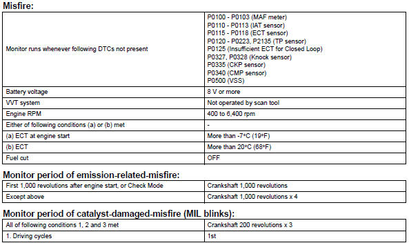

Typical malfunction thresholds
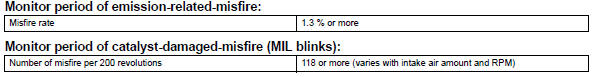
Monitor result
Refer to checking monitor status (see page es-17).
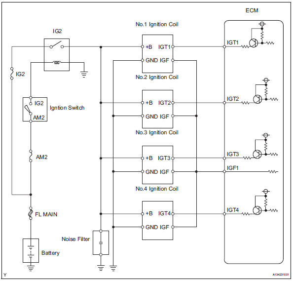
Wiring diagram
Wiring diagram of the ignition system.
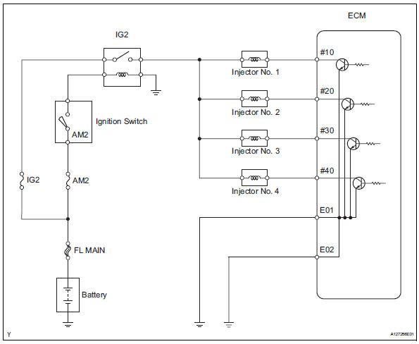
Wiring diagram of the injector circuit.
Confirmation driving pattern
- Connect the intelligent tester to the dlc3.
- Turn the ignition switch on.
- Turn the tester on.
- Record the dtc(s) and freeze frame data.
- Using the tester, switch the ecm from normal mode to check mode (see page es-38).
- Read the misfire counts of each cylinder (cyl #1 to #4) with the engine in an idling condition. If any misfire count is displayed, skip the following confirmation driving pattern.
- Drive the vehicle several times with the conditions, such as engine rpm and engine load, shown in misfire rpm and misfire load in the data list.
Hint:
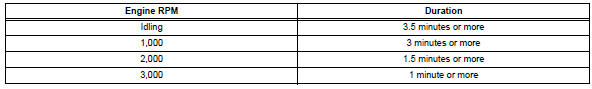
In order to store misfire dtcs, it is necessary to drive the vehicle for the period of time shown in the table below, with the misfire rpm and misfire load in the data list.
- Check whether misfires have occurred by checking dtcs and freeze frame data.
Hint:
Do not turn the ignition switch off until the stored dtc(s) and freeze frame data have been recorded.
When the ecm returns to normal mode (default), the stored dtc(s), freeze frame data and other data will be erased.
- Record the dtc(s), freeze frame data and misfire counts.
- Turn the ignition switch off and wait for at least 5 seconds.
Inspection procedure
Hint:
- If any dtcs other than misfire dtcs are output, troubleshoot those dtcs first.
- Read freeze frame data using the intelligent tester. Freeze frame data records the engine condition when malfunctions are detected. When troubleshooting, freeze frame data can help determine if the vehicle was moving or stationary, if the engine was warmed up or not, if the air-fuel ratio was lean or rich, and other data from the time the malfunction occurred.
- If the misfire does not recur when the vehicle is brought to the workshop, reproduce the conditions stored in the freeze frame data.
- If the misfire still cannot be reproduced even though the conditions
stored in the freeze frame data
have been duplicated, one of the following factors is considered to be a
possible cause of the problem:
(a)the fuel level is low.
(B)improper fuel is used.
(C)the spark plugs are dirty.
(D)the problem is complex due to multiple factors.
- After finishing repairs, check that no misfires occur in each cylinder (cyl #1, #2, #3 and #4).
- Be sure to confirm that no misfiring cylinder dtcs are set again by conducting the confirmation driving pattern, after the repairs.
- For 6 and 8 cylinder engines, the ecm intentionally does not set the
specific misfiring cylinder dtcs at
high engine rpm. If misfires only occur during high engine rpm driving, only
dtc p0300 is set.
In the event of dtc p0300 being present, perform the following operations: (a)clear the dtc (see page es-35).
(B)start the engine and conduct the confirmation driving pattern.
(C)read the misfiring rates of each cylinder or dtc(s) using the tester.
(D)repair the cylinder(s) that has a high misfiring rate or is indicated by the dtc.
(E)after finishing repairs, conduct the confirmation driving pattern again, in order to verify that dtc p0300 is not set.
- When either short ft #1 or long ft #1 in the freeze frame data is outside the range of +-20 %, the air-fuel ratio may be rich (-20 % or less) or lean (+20 % or more).
- When the coolant temp in the freeze frame data is less than 75°c (167°f), the misfires occurred only while warming up the engine.
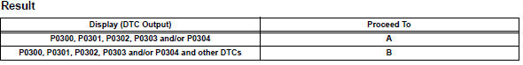
- Check any other dtcs output (in addition to misfire dtcs)
- Connect the intelligent tester to the dlc3.
- Turn the ignition switch on.
- Turn the tester on.
- Select the following menu items: diagnosis / enhanced obd ii / dtc info / current codes.
- Read dtcs.
Hint:
If any dtcs other than p0300, p0301, p0302, p0303 and p0304 are output, troubleshoot those dtcs first.

- Read value using intelligent tester (misfire rpm and misfire load)
- Connect the intelligent tester the dlc3.
- Turn the ignition switch to on and turn the tester on.
- Select the following menu items: diagnosis / enhanced obd ii / data list / misfire / misfire rpm and misfire load.
- Read and note the misfire rpm and misfire load (engine load) values.
Hint:
The misfire rpm and misfire load indicate the vehicle conditions under which the misfire occurred.

- Check pcv hose connections
Ok: pcv hose is connected correctly and is not damaged.


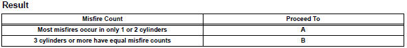
- Check misfire count (cyl #1, #2, #3 and #4)
- Connect the intelligent tester to the dlc3.
- Turn the ignition switch on.
- Turn the tester on.
- Clear dtcs (see page es-35).
- Select the following menu items: diagnosis / enhanced obd ii / data list / misfire / cyl #1, #2, #3 and #4.
- Allow the engine to idle.
- Read each value for cyl #1 to #4 displayed on the tester.
If no misfire counts occur in any cylinders, perform the following procedures:
- Shift the gear selector lever to the d position.
- Check the cyl #1 to #4.
- If misfire counts are still not displayed, perform steps
And (i) and then check the misfire counts again.
- Drive the vehicle with the misfire rpm and misfire load noted in the "read value using intelligent tester (misfire rpm and misfire load)" procedures above.
- Read the cyl #1 to #4 or dtcs displayed on the tester.
Hint:
- If it is difficult to reproduce misfires for each cylinder, check the data list item called misfire margin. Try to find vehicle driving conditions that lower the misfire margin value. Values above 30 % are considered normal.
- If the freeze frame data's record of the ect is below 75°c (167°f), the misfire may be detected only when the engine is cold.
- If the freeze frame data's record of the engine run time is below 120 seconds, the misfire may be detected immediately after the engine is started.


- Perform active test using intelligent tester (fuel cut #1 to #4)
- Allow the engine to idle.
- Select the following menu items: diagnosis / enhanced obd ii / active test / fuel cut#1 (to #4).
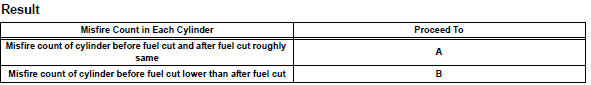
- If a cylinder has a high misfire count, cut fuel to that cylinder. Compare the misfire count of the cylinder before fuel cut and after fuel cut.
Notice:
This active test cannot be performed while the vehicle is being driven.
Hint:
If the misfire count of the cylinder before and after the fuel cut are roughly the same, the cylinder is misfiring.
If the misfire count of the cylinder before the fuel cut is lower than after the fuel cut, the cylinder misfires sometimes.


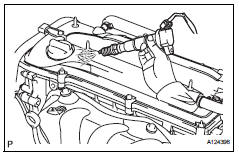
- Check spark plug
- Remove the ignition coil and the spark plug of the misfiring cylinder
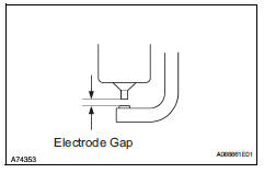
- measure the spark plug electrode gap.
Standard gap: 1.0 To 1.1 Mm (0.039 To 0.043 In.)
- Check the electrode for carbon deposits.
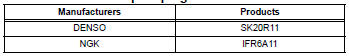
Recommended spark plug:
Notice:
If the electrode gap is larger than standard, replace the spark plug. Do not adjust the electrode gap.


- Check for sparks and ignition
- Remove the ignition coil from the cylinder head.
- Install the spark plug onto the ignition coil.
- Connect the intelligent tester to the dlc3.
- Turn the ignition switch on and turn the tester on.
- Select the following menu items: diagnosis / enhanced obd ii / active test / fuel cut all.
- Attach the spark plug assembly to the cylinder head.
- Perform the fuel cut all operation (press the right or left button to change the on).
Notice:
When fuel cut all is off and the engine is cranked, fuel injection will occur.
- Crank the engine for less than 2 seconds and check the spark.
Ok: sparks jump across electrode gap.
- Install the ignition coil.


- Check cylinder compression pressure of misfiring cylinder
- Measure the cylinder compression pressure of the misfiring cylinder.

- Change normal spark plug and check spark of misfiring cylinder
- Change the installed spark plug to a spark plug that functions normally.
- Perform a spark test.
Caution:
Always disconnect all injector connectors.
Notice:
Do not crank the engine for more than 2 seconds.
- Install the spark plug to the ignition coil and connect the ignition coil connector.
- Disconnect the injector connector.
- Ground the spark plug.
- Check if sparks occur while the engine is being cranked.
Ok: sparks jump across electrode gap.
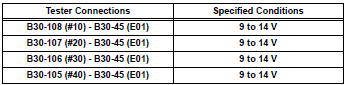
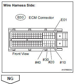
- Inspect ecm terminal of misfiring cylinder (#10, #20, #30, and /or #40 voltage)
- Disconnect the b30 ecm connector.
- Turn the ignition switch on.
- Measure the voltage between the terminals of the ecm connector.
Standard voltage

- Check harness and connector (injector - ecm)
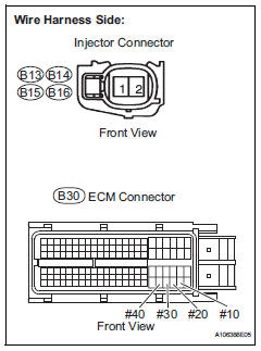
- Disconnect the injector connector (of the misfiring cylinder).
- Disconnect the b30 ecm connector.
- Turn the ignition switch on.
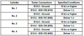
- Measure the resistance and voltage between the injector and the ecm connector terminals.
Standard voltage
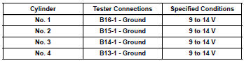
Standard resistance
- Reconnect the injector connector.
- Reconnect the ecm connector.

- Check fuel injector of misfiring cylinder
- Check the injector injection (whether fuel volume is high or low, and whether injection pattern is poor).

- Check valve clearance o
,


- Check air induction system
- Check the air induction system for vacuum leakage.
Ok: no leakage from air induction system.

- Check valve timing (see page es-77)

- Check fuel pressure
- Check the fuel pressure (see page fu-6).

- Read value using intelligent tester (coolant temp) (see page es-159)

- Read value using intelligent tester (maf) (see page es-158)

 System too
Description
The fuel trim is related to the feedback compensation value, not to the basic
injection time. The fuel trim
consists of both the short-term and the long-term fuel trims.
The sho ...
 Knock sensor 1 circuit
Description
Flat type knock sensors (non-resonant type) have structures that can detect
vibrations over a wide band
of frequencies: between approximately 6 khz and 15 khz.
A knock sensor is ...
Other materials:
Air-fuel ratio (a/f) and heated oxygen (ho2) sensor
heater monitors (front a/f and rear ho2 sensor type)
Preconditions
The monitor will not run unless:
The mil is off.
Drive pattern
Connect the intelligent tester to the dlc3.
Turn the ignition switch on.
Turn the tester on.
Clear dtcs (if set) (see page es-35).
Start the engine.
Allow the engine to idle for 10 minute ...
Maintenance data
(fuel, oil level, etc.)
Dimensions and weights
*: Unladen vehicle
Vehicle identification
Vehicle identification number
The vehicle identification number (vin) is the legal identifier for
your vehicle. This is the primary identification number for your
toyota. It is used in registering the ownership of your vehicl ...
Front suspension lower no. 1 Arm
Components
Removal
Remove front wheel
Remove hood sub-assembly
Remove the hood (see page ed-4).
Suspend engine assembly
Install the no. 1 And no. 2 Engine hangers with the
bolts as shown in the illustration.
Torque: 38 n*m (387 kgf*cm, 28 ft.*Lbf)
parts no.
...
