Toyota RAV4 (XA40) 2013-2018 Service Manual: Installation
- Install starter assembly
- Install the starter with the 2 bolts.
Torque: 37 n*m (377 kgf*cm, 27 ft.*Lbf)
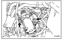
- Connect the starter connector.
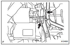
- Install the terminal nut and cover the nut with the cap.
Torque: 9.8 N*m (100 kgf*cm, 7 ft.*Lbf)
- Install battery bracket reinforcement
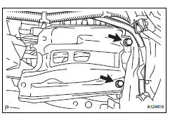
- Install the bracket reinforcement.
Torque: 19 n*m (194 kgf*cm, 14 ft.*Lbf)
- Install front battery bracket
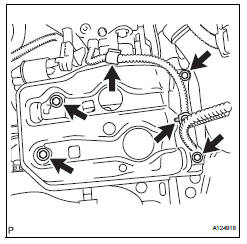
- Install the bracket front with the 4 bolts.
Torque: 19 n*m (194 kgf*cm, 14 ft.*Lbf)
- Attach the 2 wire harness clamps.
- Install battery
- Install battery insulator
- Install battery clamp
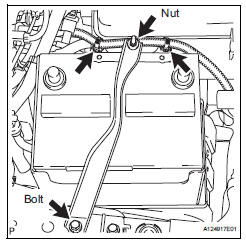
- Attach the hook of the battery clamp to the battery bracket front.
- Temporarily tighten the nut and install the bolt.
- Adjust the battery clamp's position.
- Fully tighten the nut and bolt.
Torque: 5.0 N*m (51 kgf*cm, 44 in.*Lbf)
- Attach the 2 wire harness clamps.
- Connect cable to positive battery terminal
- Connect cable to negative battery terminal
 Reassembly
Hint:
Use high-temperature grease to lubricate the bearings,
gears, return spring and steel ball when assembling the
starter.
Install planetary gear
Apply grease to the planetary gears an ...
 Starter relay
On-vehicle inspection
Disconnect cable from negative battery
terminal
Caution:
Wait at least 90 seconds after disconnecting the
cable from the negative (-) battery terminal to
prevent airb ...
Other materials:
Components
...
Test mode procedure
Hint:
By switching the skid control ecu from normal mode to
test mode, abnormality detection sensitivity is enhanced
and troubleshooting can be conducted efficiently.
Perform a sensor check in test mode after the speed
sensor or sensor rotor has been repaired or replaced.
If the igniti ...
When servicing active torque control 4wd vehicles
The active torque control 4wd rav4 is equipped
with the 4 wheel drive control system.
If incorrect preparations or test procedures are
used, the test will not only be unsuccessful, but may
be dangerous as well.
Caution:
Never accelerate or decelerate the vehicle
suddenly.
Obs ...
