Toyota RAV4 (XA40) 2013-2018 Service Manual: Reassembly
Hint:
Use high-temperature grease to lubricate the bearings, gears, return spring and steel ball when assembling the starter.
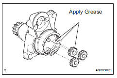
- Install planetary gear
- Apply grease to the planetary gears and pin parts of the planetary shaft.
- Install the 3 planetary gears.
- Install starter armature assembly
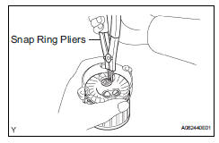
- Apply grease to the plate washer and the armature shaft.
- Install the starter armature to the starter commutator end frame.
- Using snap ring pliers, install the plate washer and a new snap ring.
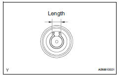
- Using a vernier caliper, measure length of the snap ring.
Maximum length: 5.0 Mm (0.197 In.)
If the length is greater than the maximum, replace it with a new snap ring.
- Install starter commutator end frame cover
- Install the end frame cover to the commutator end frame.
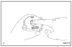
- Install starter armature plate
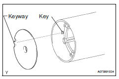
- Insert the armature plate to the starter yoke.
- Align the keyway of the starter plate with the key inside the starter yoke, and install the starter plate.
- Install starter commutator end frame assembly
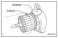
- Align the rubber of the end frame with the cutout of the starter yoke.
- Install the end frame to the starter yoke.
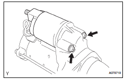
- Install starter yoke assembly
- Align the protrusion of the starter yoke with the cutout of the starter drive housing.
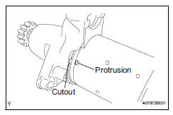
- Install the starter yoke with the 2 through-bolts.
Torque: 5.9 N*m (60 kgf*cm, 52 in.*Lbf)
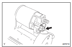
- Install magnetic switch assembly
- Apply grease to the plunger and the hook.
- Hang the plunger hook of the magnetic switch to the drive lever.
- Install the plunger and return spring.
- Install the magnetic switch with the 2 screws.
Torque: 7.5 N*m (76 kgf*cm, 66 in.*Lbf)
- Connect the lead wire to the magnetic switch with
the nut.
Torque: 10 n*m (102 kgf*cm, 7 ft.*Lbf)
 Inspection
Inspect starter assembly
Notice:
These tests must be performed within 3 to 5 seconds
to avoid burning out the coil.
Perform the pull-in test.
Disconnect the lead wire from terminal c ...
 Installation
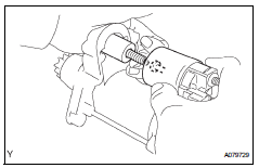
Install starter assembly
Install the starter with the 2 bolts.
Torque: 37 n*m (377 kgf*cm, 27 ft.*Lbf)
Connect the starter connector.
Install the terminal nut and cover the nu ...
Other materials:
Vc output circuit
Description
The ecm constantly generates 5 v power from the battery voltages supplied to
the +b (batt) terminal to
operate the microprocessor. The ecm also provides this power to the sensors
through the vc output
circuit.
When the vc circuit is short-circuited, the microprocessor in the ...
Releasing and stowing the seat belt (for the rear center seat)
To release the hooked buckle
“b”, push the buckle release
button.
Release button
To release the hooked plate
A insert the mechanical key
Or plate B or the
wireless key into the hole on
the buckle.
When releasing the seat belt,
retract it slowly.
Stow th ...
Terminals of ecu
Check instrument panel junction block (main body ecu)
Disconnect the ib and ie junction block connectors.
Measure the voltage and resistance of the wire
harness side connectors.
Reconnect the ib and ie junction block connector.
Measure the voltage of the wire harness ...
