Toyota RAV4 (XA40) 2013-2018 Service Manual: Short in front passenger side pretensioner squib circuit
Description
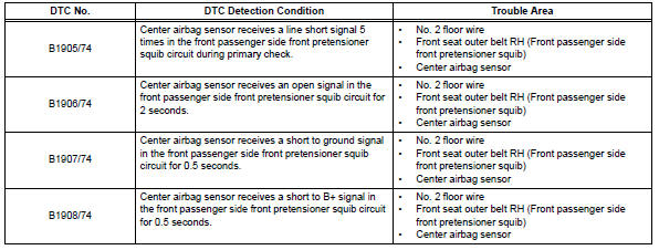
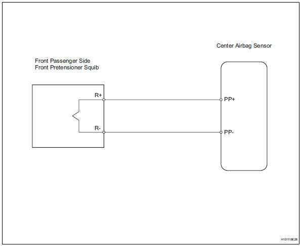
The front passenger side front pretensioner squib circuit consists of the center airbag sensor and the front seat outer belt rh.
This circuit instructs the srs to deploy when the deployment conditions are met.
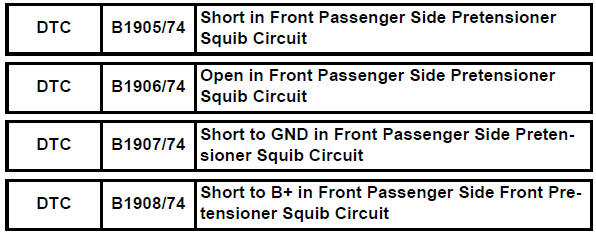
These dtcs are recorded when a malfunction is detected in the front passenger side front pretensioner squib circuit.
Wiring diagram
Inspection procedure
Hint:
- Perform the simulation method by selecting the "check mode" (signal check) with the intelligent tester (see page rs-52).
- After selecting the "check mode" (signal check), perform the simulation method by wiggling each connector of the airbag system or driving the vehicle on a city or rough road (see page rs-52).
- Check front seat outer belt assembly rh (front passenger side front pretensioner squib)
- Turn the ignition switch off.
- Disconnect the cable from the negative (-) battery terminal, and wait for at least 90 seconds.
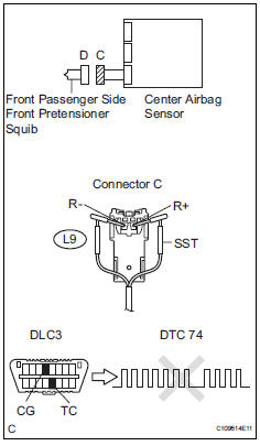
- Disconnect the connectors from the front seat outer belt rh.
- Connect the white wire side of sst to connector c.
Caution:
Never connect a tester to the front seat outer belt rh (front passenger side front pretensioner squib) for measurement, as this may lead to a serious injury due to airbag deployment.
Notice:
- Do not forcibly insert sst into the terminals of the connector when connecting.
- Insert sst straight into the terminals of the connector.
Sst 09843-18060
- Connect the cable to the negative (-) battery terminal, and wait for at least 2 seconds.
- Turn the ignition switch on, and wait for at least 60 seconds.
- Clear the dtcs (see page rs-49).
- Turn the ignition switch off.
- Turn the ignition switch on, and wait for at least 60 seconds
- Check the dtcs (see page rs-49).
Ok: dtc b1905, b1906, b1907, b1908 or 74 is not output.
Hint:
Dtcs other than dtc b1905, b1906, b1907, b1908 or 74 may be output at this time, but they are not related to this check.

- Check con3
- Turn the ignition switch off.
- Disconnect the cable from the negative (-) battery terminal, and wait for at least 90 seconds.
- Disconnect sst from connector c.
- Check that the floor wire connector (on the front seat outer belt rh side) is not damaged.
Ok: lock button is not disengaged, or the claw of the lock is not deformed or damaged.


- Check floor wire (front passenger side front pretensioner squib circuit)
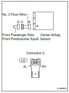
- Disconnect the connectors from the center airbag sensor.
- Connect the cable to the negative (-) battery terminal, and wait for at least 2 seconds.
- Measure the voltage of the wire harness side connector.
Standard voltage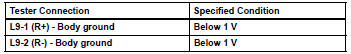
- Turn the ignition switch off.
- Disconnect the cable from the negative (-) battery terminal, and wait for at least 90 seconds.
- Measure the resistance of the wire harness side connector.
Standard resistance 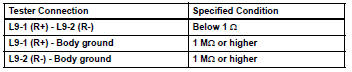
- Release the activation prevention mechanism built into connector b (see page rs-37).
- Measure the resistance of the wire harness side connector.
Standard resistance 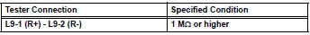


Replace center airbag sensor assembly
 Short in front driver side pretensioner squib circuit
Description
The driver side front pretensioner squib circuit consists of the center
airbag sensor and the front seat
outer belt lh.
This circuit instructs the srs to deploy when the deploym ...
 Source voltage drop
Description
The srs is equipped with a voltage-increase circuit (dc-dc converter) in the
center airbag sensor in
case the source voltage drops.
When the source voltage drops, the voltage-increa ...
Other materials:
Steering wheel
Adjustment procedure
1. Hold the steering wheel and
push the lever down.
2. Adjust to the ideal position by
moving the steering wheel
horizontally and vertically.
After adjustment, pull the lever up
to secure the steering wheel.
WARNING
â– Caution while driving
Do not adjust the steering wheel
wh ...
Rear view monitor
system
The rear view monitor system assists the driver by displaying an
image of the view behind the vehicle and fixation guide lines
while backing up, for example while parking.
The screen illustrations used in this text are intended as examples,
and may differ from the image that is actually displaye ...
Weight limits
The gross trailer weight must never exceed 1500 lb. (680 Kg).
The gross combination weight must never exceed the gcwr
described below.
2Wd models: 5985 lb. (2715 Kg)
awd models: 6100 lb. (2765 Kg)
The gross vehicle weight must
never exceed the gvwr indicated
on the certification l ...
