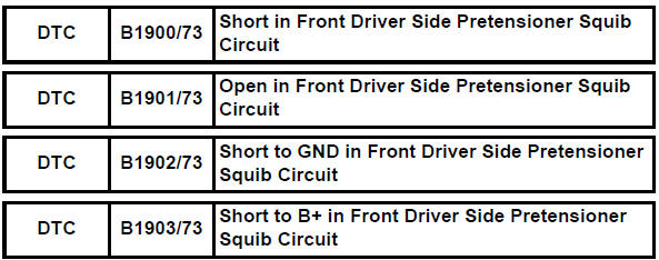
Toyota RAV4 (XA40) 2013-2018 Service Manual: Short in front driver side pretensioner squib circuit
Description
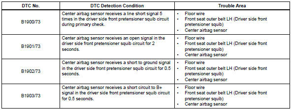
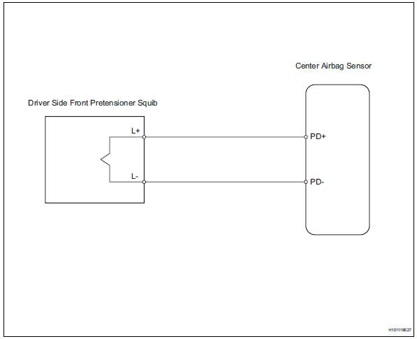
The driver side front pretensioner squib circuit consists of the center airbag sensor and the front seat outer belt lh.
This circuit instructs the srs to deploy when the deployment conditions are met.
These dtcs are recorded when a malfunction is detected in the front pretensioner squib circuit.
Wiring diagram
Inspection procedure
Hint:
- Perform the simulation method by selecting the "check mode" (signal check) with the intelligent tester (see page rs-52).
- After selecting the "check mode" (signal check), perform the simulation method by wiggling each connector of the airbag system or driving the vehicle on a city or rough road (see page rs-52).
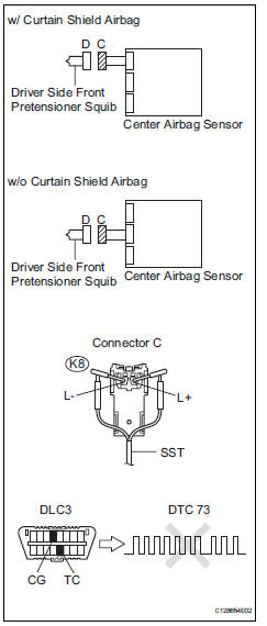
- Check front seat outer belt assembly lh (driver side front pretensioner squib)
- Turn the ignition switch off.
- Disconnect the cable from the negative (-) battery terminal, and wait for at least 90 seconds.
- Disconnect the connectors from the front seat outer belt lh.
- Connect the white wire side of sst to connector c.
Caution:
Never connect a tester to the front seat outer belt lh (driver side front pretensioner squib) for measurement, as this may lead to a serious injury due to airbag deployment.
Notice:
- Do not forcibly insert sst into the terminals of the connector when connecting.
- Insert sst straight into the terminals of the connector.
Sst 09843-18060
- Connect the cable to the negative (-) battery terminal, and wait for at least 2 seconds.
- Turn the ignition switch on, and wait for at least 60 seconds.
- Clear the dtcs (see page rs-49).
- Turn the ignition switch off.
- Turn the ignition switch on, and wait for at least 60 seconds.
- Check the dtcs (see page rs-49).
Ok: dtc b1900, b1901, b1902, b1903 or 73 is not output.
Hint:
Dtcs other than dtc b1900, b1901, b1902, b1903 or 73 may be output at this time, but they are not related to this check.

- Check connector
- Turn the ignition switch off.
- Disconnect the cable from the negative (-) battery terminal, and wait for at least 90 seconds.
- Disconnect sst from connector c.
- Check that the floor wire connector (on the driver side front seat outer belt) is not damaged.
Ok: the lock button is not disengaged, or the claw of the lock is not deformed or damaged.

- Check floor wire (driver side front pretensioner squib circuit)
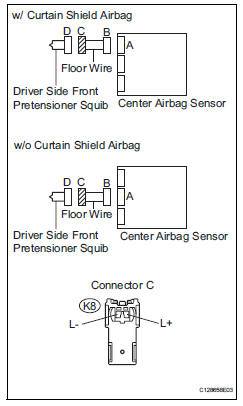
- Disconnect the connector from the center airbag sensor.
- Connect the cable to the negative (-) battery terminal, and wait for at least 2 seconds.
- Turn the ignition switch on.
- Measure the voltage of the wire harness side connector.
Standard voltage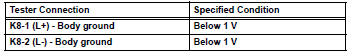
- Release the activation prevention mechanism built into connector b (see page rs-37).
- Measure the resistance of the wire harness side connector.
Standard resistance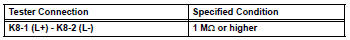

Replace center airbag sensor assembly
 Short in front passenger side curtain shield squib circuit
Description
The front passenger side curtain shield squib circuit consists of the center
airbag sensor and the curtain
shield airbag rh.
The circuit instructs the srs to deploy when the dep ...
 Short in front passenger side pretensioner squib circuit
Description
The front passenger side front pretensioner squib circuit consists of the
center airbag sensor and the front
seat outer belt rh.
This circuit instructs the srs to deploy whe ...
Other materials:
Automatic
air conditioning system
Air outlets and fan speed are automatically adjusted according
to the temperature setting.
Driver’s side temperature control
dial
Automatic mode button
Micro dust and pollen filter
mode button
Driver’s side temperature setting
display
Fan speed display
Air outlet display ...
General maintenance (2006/01- )
General notes
Maintenance requirements vary depending on the
country.
Check the maintenance schedule in the owner's
manual supplement.
Following the maintenance schedule is mandatory.
Determine the appropriate time to service the vehicle
using either miles driven or time elapsed ...
Forward clutch
Components
Disassembly
Inspect forward clutch (see page ax-227)
Remove forward multiple disc clutch disc
Using a screwdriver, remove the snap ring.
Remove the flange , 5 discs and 5 plates from the
input shaft.
Inspect forward multiple disc clutch disc (see page ax-228 ...
