Toyota RAV4 (XA40) 2013-2018 Service Manual: Source voltage drop
Description
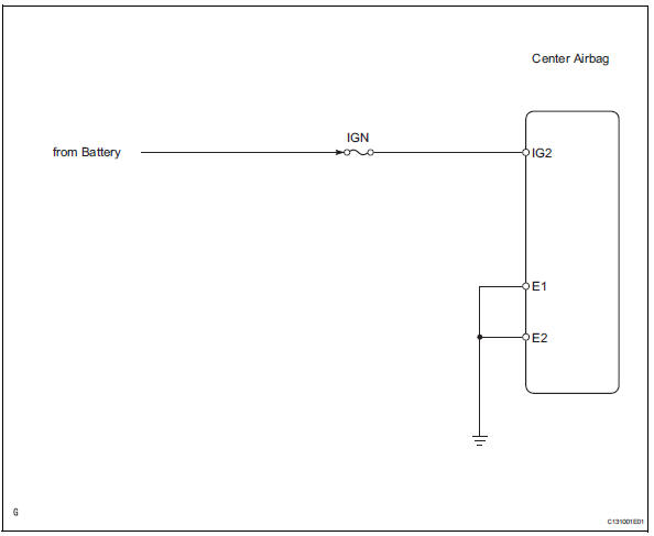
The srs is equipped with a voltage-increase circuit (dc-dc converter) in the center airbag sensor in case the source voltage drops.
When the source voltage drops, the voltage-increase circuit (dc-dc converter) functions to increase the voltage of the srs to a normal working level.
A malfunction in this circuit is displayed differently from other codes, in the fact that no dtcs are recorded. With a normal system code present, the source voltage drop is indicated when the srs warning light comes on.
A malfunction in this circuit is not recorded in the center airbag sensor .
The srs warning light automatically goes off when the source voltage returns to normal.
Wiring diagram
Inspection procedure
- Check wire harness (center airbag sensor assembly - battery)
- Turn the ignition switch off.
- Disconnect the negative (-) terminal cable from the battery, and wait for at least 90 seconds.
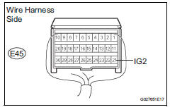
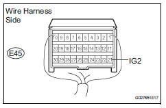
- Disconnect the e45 connector from the center airbag sensor .
- Connect the negative (-) terminal cable to the battery, and wait for at least 2 seconds.
- Measure the voltage of the wire harness side connectors.
Standard voltage 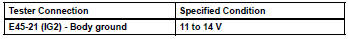

- Check wire harness (center airbag sensor assembly - body ground)
- Measure the resistance of the wire harness side connectors.
Standard resistance 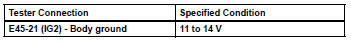

- Check wire harness (center airbag sensor assembly - body ground)
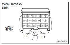
- Measure the resistance of the wire harness side connectors.
Standard resistance 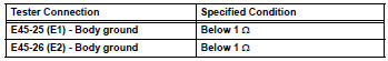

- Check srs warning light
- Turn the ignition switch off.
- Disconnect the negative (-) terminal cable from the battery, and wait for at least 90 seconds.
- Connect the e45 center airbag sensor connector.
- Connect the negative (-) terminal cable to the battery, and wait for at least 2 seconds.
- Turn the ignition switch on, and wait for at least 6 seconds.
- Operate all components of the electrical system (defogger, wiper, headlight, heater, blower, etc.) And check that the srs warning light does not come on.
Ok: srs warning light does not come on.

End
 Short in front passenger side pretensioner squib circuit
Description
The front passenger side front pretensioner squib circuit consists of the
center airbag sensor and the front
seat outer belt rh.
This circuit instructs the srs to deploy whe ...
 Srs warning light remains on
Description
The srs warning light is located on the combination meter.
When the srs is normal, the srs warning light comes on for approximately 6
seconds after the ignition
switch is turned fro ...
Other materials:
Rear wheel alignment
adjustment
Inspect tire
Inspect the tire (see page tw-1).
Measure vehicle height
Measure the vehicle height (see page sp-3).
Inspect toe-in
Standard toe-in
If the toe-in is not within the specified range, inspect the
suspension parts and replace them if necessar ...
Ig power supply voltage malfunction
Description
The power steering ecu distinguishes the ignition switch status as on or off
through the ig power
source circuit.
Wiring diagram
Inspection procedure
Read value of intelligent tester (ig power supply)
Connect the intelligent tester (with can vim) to the
dlc3.
...
PKSB (Parking Support
Brake)
The Parking Support Brake
system consists of the following
functions that operate
when driving at a low
speed or backing up, such
as when parking. When the
system determines that the
possibility of a collision
with a detected object is
high, a warning operates to
urge the driver to take evasive
acti ...
