Toyota RAV4 (XA40) 2013-2018 Service Manual: Srs warning light remains on
Description
The srs warning light is located on the combination meter.
When the srs is normal, the srs warning light comes on for approximately 6 seconds after the ignition switch is turned from off to on, and then goes off automatically.
If there is a malfunction in the srs, the srs warning light comes on to inform the driver of a problem.
When terminals tc and cg of the dlc3 are connected, the dtc is displayed by blinking the srs warning light.
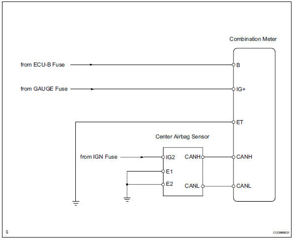
The srs is equipped with a voltage-increase circuit (dc-dc converter) in the center airbag sensor in case the source voltage drops.
When the battery voltage drops, the voltage-increase circuit (dc-dc converter) functions to increase the voltage of the srs to normal voltage.
A malfunction in this circuit is not recorded in the center airbag sensor . The srs warning light automatically goes off when the source voltage returns to normal.
The signal to illuminate the srs warning light is transmitted from the center airbag sensor to the combination meter through the multiplex communication system.
Wiring diagram
Inspection procedure
Check battery
- Measure the voltage of the battery.
Standard voltage: 11 to 14 v

- Check connector
- Turn the ignition switch off.
- Disconnect the negative (-) terminal cable from the battery, and wait for at least 90 seconds.
- Check that the connectors are properly connected to the center airbag sensor and combination meter.
Ok: the connectors are properly connected.

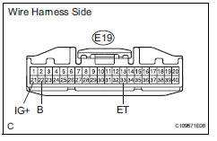
- Check wire harness (source voltage of center airbag sensor assembly)
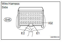
- Disconnect the e45 connector from the center airbag sensor .
- Connect the negative (-) terminal cable to the battery, and wait for at least 2 seconds.
- Turn the ignition switch on.
- Operate all components of the electrical system (defogger, wipers, headlight, heater blower, etc.).
- Measure the voltage of the wire harness side connectors.
Standard voltage 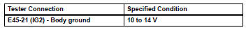
- Turn the ignition switch off.
- Measure the resistance of the wire harness side connectors.
Standard resistance 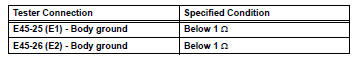

- Check wire harness (source voltage of combination meter)
- Disconnect the negative (-) terminal cable from the battery, and wait for at least 90 seconds.
- Disconnect the e19 connector from the combination meter.
- Connect the negative (-) terminal cable to the battery, and wait for at least 2 seconds.
- Turn the ignition switch on.
- Measure the voltage of the wire harness side connectors.
Standard voltage 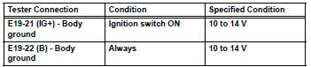
- Turn the ignition switch off.
- Measure the resistance of the wire harness side connectors.
Standard resistance 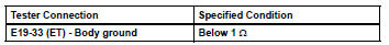

- Check srs warning light
- Turn the ignition switch off.
- Disconnect the negative (-) terminal cable from the battery, and wait for at least 90 seconds.
- Connect the e19 connector to the combination meter.
- Connect the negative (-) terminal cable to the battery, and wait for at least 2 seconds.
- Turn the ignition switch on.
- Check the srs warning light condition.
Ok: after the primary check period, srs warning light goes off for approximately 10 seconds, and turning it on is continued.
Hint:
The primary check period shows approximately 6 seconds after the ignition switch is on.

Replace center airbag sensor assembly
 Source voltage drop
Description
The srs is equipped with a voltage-increase circuit (dc-dc converter) in the
center airbag sensor in
case the source voltage drops.
When the source voltage drops, the voltage-increa ...
 Srs warning light does not come on
Description
The srs warning light is located on the combination meter.
When the srs is normal, the srs warning light comes on for approximately 6
seconds after the ignition
switch is turned fro ...
Other materials:
Inspection
Inspect oil pump assembly
Turn the drive gear with 2 screwdrivers and make
sure it rotates smoothly.
Notice:
Be careful not to damage the oil seal lip.
Inspect clearance of oil pump assembly
Push the driven gear to one side of the body. Using
a feeler gauge, measur ...
How to proceed with troubleshooting (2006/01- )
Hint:
Use these procedures to troubleshoot the air conditioning
system.
*: Use the intelligent tester.
Vehicle brought to workshop
Customer problem analysis and symptom check
Inspect battery voltage
Standard voltage:
11 to 14 v
If the voltage is below 11 v, recharg ...
Ambient temperature sensor circuit
Description
The ambient temperature sensor is installed in the front part of the
condenser to detect the ambient
temperature and control the air conditioner. The sensor is connected to the
combination meter and
detects fluctuations in the ambient temperature. This data is used for
contr ...
