Toyota RAV4 (XA40) 2013-2018 Service Manual: Parking brake system
Problem symptoms table
Hint:
Use the table below to help determine the cause of the problem symptom. The potential causes of the symptoms are listed in order of probability in the "suspected area" column of the table. Check each symptom by checking the suspected areas in the order they are listed. Replace parts as necessary.
Adjustment
- Check parking brake lever travel
- Pull the lever upward with a force of approximately 200 n (20 kgf, 44 lbf) and count the number of clicks.
Ok: 7 to 9 clicks (without rear brake dragging)
- Remove upper rear console panel subassembly (see page ip-19)
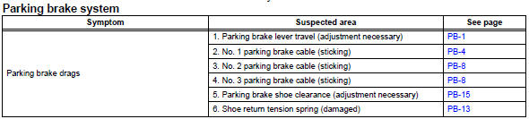
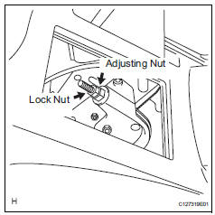
- Loosen lock nut and no. 1 Wire adjusting nut
- Remove rear wheel
- Adjust parking brake shoe clearance (see page pb-17)
- Install rear wheel torque: 103 n*m (1,050 kgf*cm, 76 ft.*Lbf)
- Adjust parking brake lever travel
- Turn the no. 1 Wire adjusting nut until the lever travel is correct.
Ok: 7 to 9 clicks (without rear brake dragging) <lever pulling force: approximately 200 n (20 kgf, 44 lbf)>
- Tighten the lock nut.
Torque: 6.0 N*m (61 kgf*cm, 53 in.*Lbf)
- Operate the parking brake lever 3 to 4 times, and check the parking brake lever travel.
Ok: 7 to 9 clicks (without rear brake dragging) <lever pulling force: approximately 200 n (20 kgf, 44 lbf)>
- When operating the parking brake lever, check that the brake warning light illuminates at the first click.
Standard condition: brake warning light always illuminates at the first click.
 Parking brake
...
 Parking brake lever
Components
On-vehicle inspection
Check parking brake switch assembly
Remove the rear console box (see page ip-16).
Hint:
Refer to the procedures from the removal of the no.
...
Other materials:
Driver side seat belt warning light does not operate
Description
When the ignition switch is on, the center airbag sensor transmits front seat
inner belt status signals to
the combination meter through the can bus line. If the driver seat belt is not
fastened, the combination
meter blinks the driver side seat belt warning light. If the seat bel ...
Pressure control solenoid "A" electrical (shift solenoid valve sl1)
Description
Shifting from 1st to o/d is performed in combination with the on and off
operation of the shift solenoid
valves sl1 and sl2, which are controlled by the ecm. If an open or short circuit
occurs in any of the shift
solenoid valves, the ecm controls the remaining normal shift soleno ...
Engine coolant temperature circuit range / performance problem
Description
Refer to dtc p0115 (see page es-105).
Monitor description
Engine coolant temperature (ect) sensor cold start monitor
When a cold engine start is performed and then the engine is warmed up, if
the ect sensor value does
not change, it is determined that a malfunction has occ ...
