Toyota RAV4 (XA40) 2013-2018 Service Manual: Srs warning light does not come on
Description
The srs warning light is located on the combination meter.
When the srs is normal, the srs warning light comes on for approximately 6 seconds after the ignition switch is turned from off to on, and then goes off automatically.
If there is a malfunction in the srs, the srs warning light comes on to inform the driver of a problem.
When terminals tc and cg of the dlc3 are connected, the dtc is displayed by blinking the srs warning light.
The srs is equipped with a voltage-increase circuit (dc-dc converter) in the center airbag sensor in case the source voltage drops.
When the battery voltage drops, the voltage-increase circuit (dc-dc converter) functions to increase the voltage of the srs to normal voltage.
A malfunction in this circuit is not recorded in the center airbag sensor . The srs warning light automatically goes off when the source voltage returns to normal.
The signal to illuminate the srs warning light is transmitted from the center airbag sensor to the combination meter through the multiplex communication system.
Wiring diagram
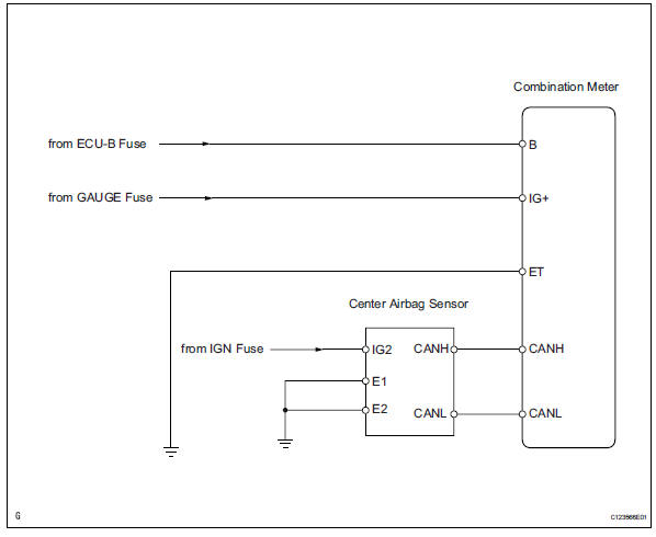
Inspection procedure
- Check battery
- Measure the voltage of the battery.
Standard voltage: 11 to 14 v

- Check connectors
- Turn the ignition switch off.
- Disconnect the negative (-) terminal cable from the battery, and wait for at least 90 seconds.
- Check that the e19 connectors are properly connected to the center airbag sensor and the combination meter.
Ok: the connectors are properly connected.

- Check wire harness (source voltage of combination meter)
- Turn the ignition switch off.
- Disconnect the negative (-) terminal cable from the battery, and wait for at least 90 seconds.
- Disconnect the connector from the combination meter.
- Connect the negative (-) terminal cable to the battery, and wait for at least 2 seconds.
- Turn the ignition switch on.
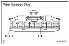
- Measure the voltage of the wire harness side connectors.
Standard voltage 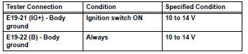
- Turn the ignition switch off.
- Measure the resistance of the wire harness side connectors.
Standard resistance 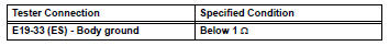

- Check srs warning light
- Turn the ignition switch off.
- Disconnect the negative (-) terminal cable from the battery, and wait for at least 90 seconds.
- Connect the e19 connector to the combination meter.
- Connect the negative (-) terminal cable to the battery, and wait for at least 2 seconds.
- Turn the ignition switch on.
- Check the srs warning light condition.
Ok: the srs warning light does not come on.

Replace center airbag sensor assembly
 Srs warning light remains on
Description
The srs warning light is located on the combination meter.
When the srs is normal, the srs warning light comes on for approximately 6
seconds after the ignition
switch is turned fro ...
 Tc and cg terminal circuit
Description
Dtc output mode is set by connecting terminals tc and cg of the dlc3.
The dtcs are displayed by blinking the srs warning light.
Hint:
Make sure that dtc b1281 has not been output. ...
Other materials:
Using the automatic air conditioning system
Press .
The dehumidification function begins to operate. Air outlets and fan speed
are automatically adjusted according to the temperature setting and
humidity.
Turn clockwise to
increases the temperature and turn
counterclockwise to decreases
the temperature.
T ...
Clock
The clock can be adjusted by pressing the buttons.
Adjusts the hours.
Adjusts the minutes.
The clock is displayed when
Vehicles without a smart key system
The engine switch is in the ŌĆ£accŌĆØ or ŌĆ£onŌĆØ position.
Vehicles with a smart key system
The engine switch is in a ...
Shift lock system
Parts location
System diagram
On-vehicle inspection
Check shift lock operation
Move the shift lever to p.
Turn the ignition switch off.
Check that the shift lever cannot be moved to any
position other than p.
Turn the ignition switch on, depress the brake
pedal and chec ...
