Toyota RAV4 (XA40) 2013-2018 Service Manual: Brake switch "A" / "B" correlation
![]()
Description
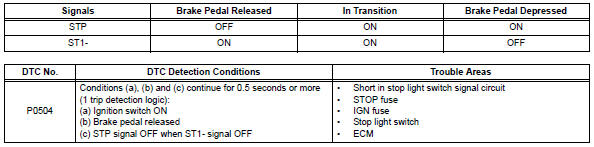
The stop light switch is a duplex system that transmits two signals: stp and st1-. These two signals are used by the ecm to monitor whether or not the brake system is working properly. If the signals, which indicate the brake pedal is being depressed and released, are detected simultaneously, the ecm interprets this as a malfunction in the stop light switch and sets the dtc.
Hint:
The normal conditions are as shown in the table below. The signals can be read using the intelligent tester.
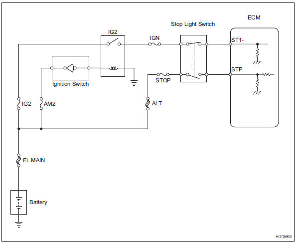
Wiring diagram
Inspection procedure
Hint:
- Read freeze frame data using the intelligent tester. Freeze frame data records the engine condition when malfunctions are detected. When troubleshooting, freeze frame data can help determine if the vehicle was moving or stationary, if the engine was warmed up or not, if the air-fuel ratio was lean or rich, and other data from the time the malfunction occurred.
- Stp signal conditions can be checked using the intelligent tester.
- Connect the intelligent tester to the dlc3.
- Turn the ignition switch on.
- Turn the tester on.
- Select the following menu items: diagnosis / enhanced obd ii / data list / primary / stop light sw.
- Check the stp signal when the brake pedal is depressed and released.

- Check stop light switch assembly (terminal b voltage)
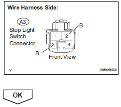
- Disconnect the a3 stop light switch connector.
- Turn the ignition switch on.
- Measure the voltage between the terminals of the a3 stop light switch connector and body ground.
Standard voltage 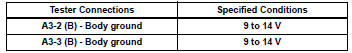
- Reconnect the stop light switch connector.
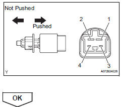
- Inspect stop light switch assembly
- Remove the stop light switch.
- Check the resistance.
Standard resistance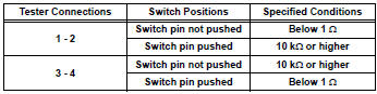
- Reinstall the stop light switch.
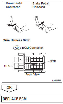
- Check ecm (stp and st1 - voltage)
- Disconnect the a9 ecm connector.
- Turn the ignition switch on.
- Measure the voltage between the terminals st1- and stp of the a9 ecm connector and body ground.
standard voltage 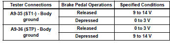
- Reconnect the ecm connector.
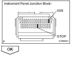
- Inspect fuse (stop and ign fuse)
- Remove the stop and ign fuses from the instrument panel junction block.
- Measure the resistance.
Standard resistance:
below 1 
- Reinstall the stop and ign fuses.
 Vehicle speed sensor "A"
description
The speed sensor detects the wheel speed and sends the appropriate signals to
the skid control ecu.
The skid control ecu converts these wheel speed signals into a 4-pulse signal ...
 Idle control system malfunction
Description
The idling speed is controlled by the etcs (electronic throttle control
system). The etcs is comprised
of: 1) the one valve type throttle body; 2) the throttle actuator, which
op ...
Other materials:
Moon roof
Use the overhead switches
to open and close the moon
roof and tilt it up and down.
Operating the moon roof
â– Opening and closing
Opens the moon roof*
The moon roof stops slightly before
the fully open position to reduce
wind noise.
Press the switch again to fully open
the moon roof.
Close ...
Pressure control solenoid "A " performance (shift solenoid valve sl1)
Description
The ecm uses signals from the vehicle speed sensor to detect the actual gear
position (1st, 2nd, 3rd or
o/d gear).
Then the ecm compares the actual gear with the shift schedule in the ecm memory
to detect mechanical
problems of the shift solenoid valves, valve body or automatic ...
Rear occupant classification sensor lh circuit malfunction
Description
The rear occupant classification sensor lh circuit consists of the occupant
classification ecu and the rear
occupant classification sensor lh.
Dtc b1782 is recorded when a malfunction is detected in the rear occupant
classification sensor lh
circuit.
Wiring diagram
...
