Toyota RAV4 (XA40) 2013-2018 Service Manual: Open in pump motor circuit
![]()
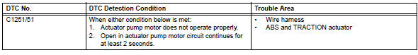
Description
The motor relay drives the pump motor based on a signal from the skid control ecu.
Wiring diagram
Refer to dtc c0273/13, c0274/14, c1361/91 (see page bc-79).
Inspection procedure
- Perform active test by intelligent tester (motor relay)
- Select the active test, generate a control command, and then check that the abs motor relay operates.

Ok: operation sound of abs motor is heard.

- Reconfirm dtc
- Clear the dtc (see page bc-47).
- Start the engine.
- Drive the vehicle at a speed of 6 km/h (4 mph) or more for several seconds.
- Check if the same dtc is output (see page bc-47).
Result 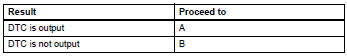

Replace abs and traction actuator assembly
- Inspect fuse (abs1)
- Remove the abs1 h-fuse from the engine room no. 1 Relay block.
- Measure the resistance of the fuse.
Standard resistance:
below 1 


- Check wire harness (skid control ecu - battery and body ground)
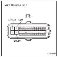
- Disconnect the a19 connector.
- Measure the resistance of the wire harness side connector.
Standard resistance 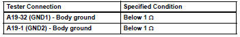
- Measure the voltage of the wire harness side connector.
Standard voltage 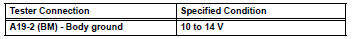

Replace abs and traction actuator assembly
 Open in stop light switch circuit
Description
The skid control ecu detects the brake operating conditions through a signal
transmitted by the stop light
switch. The skid control ecu incorporates an open circuit detection circuit. ...
 Brake pedal load sensing switch
Description
The brake pedal load sensing switch is turned on when the brake pedal is
depressed with force exceeding
a predetermined level.
The skid control ecu detects if the brake pedal is dep ...
Other materials:
Data list
Hint:
By reading the data list displayed on an intelligent
tester, values can be checked, including those of the
switches, sensors, and actuators, without removing any
parts. Reading the data list as the first step of
troubleshooting is one method of shortening diagnostic
time.
Notice:
In th ...
Tire pressure warning valve and transmitter
Components
Removal
Remove front tire
Remove rear tire
Remove tire pressure warning valve subassembly
Remove the valve core and cap, and release air
from the tire.
After ensuring that air is sufficiently released,
remove the nut and washer that are used to fix the
tire pres ...
Seat heater switch
Components
Removal
Disconnect cable from negative battery
terminal
Caution:
Wait at least 90 seconds after disconnecting the
cable from the negative (-) battery terminal to
prevent airbag and seat belt pretensioner activation.
Remove switch base (see page ip-18)
Remove seat he ...
