Toyota RAV4 (XA40) 2013-2018 Service Manual: Brake pedal load sensing switch
Description
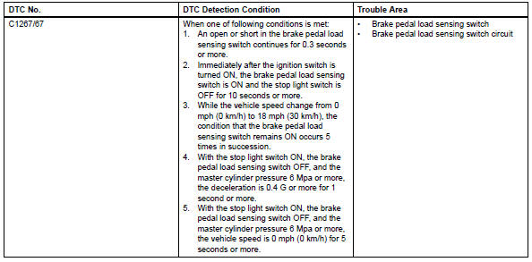
The brake pedal load sensing switch is turned on when the brake pedal is depressed with force exceeding a predetermined level.
The skid control ecu detects if the brake pedal is depressed or not via this circuit.
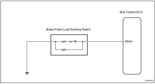
Wiring diagram
Inspection procedure
Notice:
When replacing the brake actuator assembly, perform zero point calibration (see page bc-24).
Hint:
If dtc c1249/49 is output, repair it before repairing dtc c1267/67 based on the flowchart below.
- Read value of intelligent tester (brake pedal load sensing switch)
- Check the data list for proper functioning of the brake pedal load sensing switch.
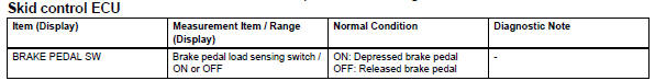
Ok: on (brake pedal is depressed) appears on the screen.


- Inspect brake pedal load sensing switch
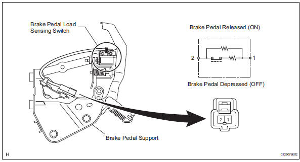
Notice:
- Do not remove the brake pedal load sensing switch from the brake pedal.
- When there is a malfunction in the brake pedal load sensing switch, replace the brake pedal.
- Turn the ignition switch off.
- Disconnect the brake pedal load sensing switch connector.
- Measure the resistance of the switch.
Standard resistance


- Check wire harness (skid control ecu - brake pedal load sensing switch)
- Disconnect the a19 ecu connector.
- Measure the resistance of the wire harness side connectors.
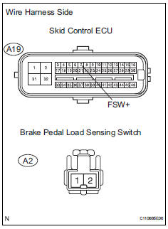
Standard resistance 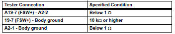

- Reconfirm dtc
- Clear the dtc (see page bc-47).
- Check if the same dtc is recorded (see page bc-47).
Result 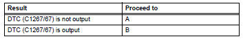

Use simulation method to check
 Open in pump motor circuit
Description
The motor relay drives the pump motor based on a signal from the skid control
ecu.
Wiring diagram
Refer to dtc c0273/13, c0274/14, c1361/91 (see page bc-79).
Inspection proce ...
 Steering angle sensor zero point malfunction
Description
The skid control ecu learns the steering sensor zero point every time the
ignition switch is turned on and
the vehicle is driven at 35 km/h (22 mph) or more for approximately 5 sec ...
Other materials:
The keys
The following keys are provided with the vehicle.
Vehicles without a smart key system (type a)
Master keys
Operating the wireless remote control
function
Valet key
Key number plate
Vehicles without a smart key system (type b)
Master keys
Operating the wireless r ...
Location of the interior lights
Rear interior light
Front interior lights/personal lights
Open tray lights (if equipped)*
Footwell lights (if equipped)*
Front cup holder lights (if equipped)*
*: These lights turn on when a door is unlocked.
When the shift lever is in a position other than P, the brightness of these
ligh ...
Air inlet damper control servo motor circuit
Description
The damper servo (air inlet control) sends pulse signals to indicate the
damper position to the air
conditioning amplifier. The air conditioning amplifier activates the motor
(normal or reverse) based on
these signals to move the air inlet control damper to the appropriate pos ...
