Toyota RAV4 (XA40) 2013-2018 Service Manual: Steering angle sensor zero point malfunction
![]()
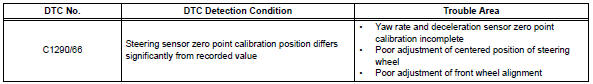
Description
The skid control ecu learns the steering sensor zero point every time the ignition switch is turned on and the vehicle is driven at 35 km/h (22 mph) or more for approximately 5 seconds. The ecu also stores the previous zero point.
If front wheel alignment or the steering wheel position is adjusted without disconnecting the negative battery terminal, or if the yaw rate and deceleration sensor zero point is not set after the adjustments have been completed, the skid control ecu detects the difference between the previously stored zero point and the newly learned zero point and outputs this dtc to indicate a poor adjustment.
Indication of the steering sensor zero point malfunction is canceled by turning the ignition switch off.
Inspection procedure
Notice:
When replacing the abs and traction actuator, perform zero point calibration (see page bc-24).
- Perform yaw rate and deceleration sensor zero point calibration
- Perform the zero point calibration of the yaw rate and deceleration sensor (see page bc-24).
Hint:
- When the stored zero point of the yaw rate and deceleration sensor is erased, the steering sensor zero point is also erased.
- If the zero point and output value of the yaw rate and deceleration sensor and the output values of the speed sensors are not normal, the steering sensor zero point cannot be learned normally even if the vehicle is driven straight ahead at 35 km/h (22 mph) or more.

- Check steering sensor
- Drive the vehicle straight ahead at 35 km/h (22 mph) or more for 5 seconds or more.
- Check that the centered position of the steering wheel is correctly set while driving straight ahead.
Hint:
If the front wheel alignment and steering position are adjusted due to an incorrectly centered position of the steering wheel, set the yaw rate and deceleration sensor zero point again after the adjustments are completed.
Ok: the center position of the steering wheel is correctly set.


- Reconfirm dtc
- Turn the ignition switch off.
- Clear the dtc (see page bc-47).
- Check if the same dtc is recorded (see page bc-47).
Result 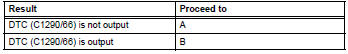

Use simulation method to check
 Brake pedal load sensing switch
Description
The brake pedal load sensing switch is turned on when the brake pedal is
depressed with force exceeding
a predetermined level.
The skid control ecu detects if the brake pedal is dep ...
 Different diameter tire malfunction
Description
The skid control ecu measures the speed of each wheel by receiving signals
from the speed sensor.
These signals are used for recognizing that all 4 wheels are operating properly. ...
Other materials:
Replacement
Replace timing chain cover oil seal
Using a screwdriver and hammer, tap out the oil
seal.
Place the oil seal retainer on wooden blocks.
Apply multi-purpose grease to the lip of a new oil
seal.
Notice:
Keep the lip free of foreign objects.
Using sst and a hammer, tap in a ...
Folding the mirrors
Push the mirror back in the direction
of the vehicle’s rear.
Mirror angle can be adjusted when
Vehicles without a smart key system
The engine switch is in the “acc” or “on” position.
Vehicles with a smart key system
The engine switch is in accessory or ignition on mode. ...
Short in front passenger side - side squib circuit
Description
The front passenger side - side squib circuit consists of the center airbag
sensor and the front seat side
airbag rh.
The circuit instructs the srs to deploy when the deployment conditions are met.
These dtcs are recorded when a malfunction is detected in the front passenge ...
