Toyota RAV4 (XA40) 2013-2018 Service Manual: Vsc warning light remains on
Description
The skid control ecu is connected to the combination meter via the can communication system.
W/o multi information display: if the skid control ecu stores any dtcs which relate to the vsc system, the vsc warning light comes on in the combination meter.
W/ multi information display: if the skid control ecu stores any dtcs which relate to the vsc system, the master caution indicator light comes on and the warning message is displayed on the multi information display in the combination meter.
Wiring diagram
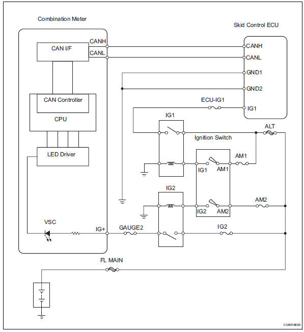
Inspection procedure
Notice:
When replacing the abs and traction actuator, perform the zero point calibration (see page bc- 24).
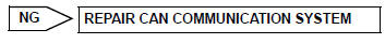
- Check can communication system
- Check if the can communication system dtc is output (see page bc-47).
Result 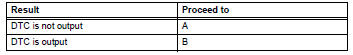

- Inspect skid control ecu connector
- Check if the skid control ecu connector is securely connected.
Ok: the connector is securely connected.

- Check combination meter assembly
- Check the combination meter (see page me-15).

Replace abs and traction actuator assembly
 Abs warning light does not come on
Wiring diagram
Refer to the abs warning light circuit (see page bc-135).
Inspection procedure
Check can communication system
Check if the can communication system dtc is output
(see page ...
 Vsc warning light does not come on
Description
Refer to the description of "vsc warning light remains on" (see page bc-139).
Wiring diagram
Refer to the vsc warning light circuit (see page bc-140).
Inspection procedure
N ...
Other materials:
Spiral cable
Components
Removal
Caution:
Be sure to read the precautionary notices concerning the
srs airbag system before servicing it (see page rs-1).
Disconnect cable from negative battery
terminal
Caution:
Wait at least 90 seconds after disconnecting the
cable from the negative (-) battery ...
If the electronic key does
not operate properly (vehicles
with smart key system)
If communication between
the electronic key and vehicle
is interrupted or the electronic key cannot
be used because the battery
is depleted, the smart key
system and wireless remote
control cannot be used. In
such cases, the doors can
be opened and the engine
can be started by following
the procedur ...
Valve body assembly
Components
Removal
Disconnect cable from negative battery
terminal
Caution:
Wait at least 90 seconds after disconnecting the
cable from the negative (-) battery terminal to
prevent airbag and seat belt pretensioner activation.
Remove no. 1 Engine under cover
Drain automati ...
