Toyota RAV4 (XA40) 2013-2018 Service Manual: Vsc warning light does not come on
Description
Refer to the description of "vsc warning light remains on" (see page bc-139).
Wiring diagram
Refer to the vsc warning light circuit (see page bc-140).
Inspection procedure
Notice:
When replacing the abs and traction actuator, perform the zero point calibration (see page bc- 24).
- Inspect can communication system
- Check if the can communication system dtc is output (see page bc-47).
Result 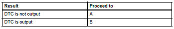

- Perform active test by intelligent tester (vsc warning light)
- Select the active test, generate a control command, and then check that the vsc warning light operates.

Ok: the vsc warning light turns on or off.

- Check combination meter assembly
- Check the combination meter (see page ca-34).

Replace abs and traction actuator assembly
 Vsc warning light remains on
Description
The skid control ecu is connected to the combination meter via the can
communication system.
W/o multi information display:
if the skid control ecu stores any dtcs which relate to t ...
 Brake warning light remains on
Description
If any of the following conditions are detected, the brake warning light
remains on:
The ecu connectors are disconnected from the skid control ecu.
The brake fluid level is insuff ...
Other materials:
The keys
The following keys are provided with the vehicle.
Vehicles without a smart key system (type a)
Master keys
Operating the wireless remote control
function
Valet key
Key number plate
Vehicles without a smart key system (type b)
Master keys
Operating the wireless r ...
Reassembly
Install cooler (solar sensor) thermistor
(for automatic air conditioning system)
Install automatic light control sensor
(for automatic light control system)
Install front passenger airbag assembly
(see page rs-351)
Install no. 2 Instrument panel register
assembly
Install no. 1 Ins ...
Brake Hold
The brake hold system
keeps the brake applied
when the shift lever is in D,
S or N with the system on
and the brake pedal has
been depressed to stop the
vehicle. The system
releases the brake when the
accelerator pedal is
depressed with the shift
lever in D or S to allow
smooth start off.
Enabling t ...
