Toyota RAV4 (XA40) 2013-2018 Service Manual: How to proceed with troubleshooting (2005/11-2006/01)
Hint:
- Use these procedures to troubleshoot the air conditioning system.
- *: Use the intelligent tester.
- Vehicle brought to workshop

- Customer problem analysis and symptom check

- Inspect battery voltage
Standard voltage: 11 to 14 v
If the voltage is below 11 v, recharge or replace the battery before proceeding.

- Check can communication system*
- Use the intelligent tester to check if the can communication system is functioning.
Result 


- Check dtc or check sensor check code through panel diagnosis*
- Check dtcs or sensor check codes.
- Write down the dtcs or sensor check codes.
- Clear the dtcs or sensor check codes.
- Check whether the dtcs or sensor check codes recur.
- Reproduce the problem symptoms in accordance with the dtcs or sensor check codes that were written down, and check whether the dtcs or sensor check codes recur.
Hint:
Refer to the dtc chart when any dtcs or sensor check codes are output.
Result 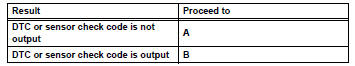


- Refer to problem symptoms table
Result 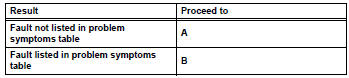


- Overall analysis and troubleshooting*
- Data list / active test (see page ac-34)
- Panel diagnosis (indicator check) (see page ac-31)
- Panel diagnosis (actuator check) (see page ac-31)
- Panel diagnosis (sensor check) (see page ac-31)
- Terminals of ecu (see page ac-24)

- Adjust, repair or replace

- Confirmation test

End
 System description
General
The air conditioning system has the following
features:
In accordance with the temperature set using the
temperature control switch, the air conditioning
amplifier determi ...
 How to proceed with troubleshooting (2006/01- )
Hint:
Use these procedures to troubleshoot the air conditioning
system.
*: Use the intelligent tester.
Vehicle brought to workshop
Customer problem analysis and symptom check
...
Other materials:
Throttle / pedal position sensor / switch "d" circuit range / performance
Description
Hint:
Refer to dtc p2120 (see page es-282).
Monitor description
When the difference between the output voltages of vpa and vpa2 deviates from
the standard, the ecm
determines that the accelerator pedal position (app) sensor is malfunctioning.
The ecm turns on the mil
and th ...
Data list / active test
Read data list
Hint:
Using the intelligent tester's data list allows switch,
sensor, actuator, and other item values to be read
without removing any parts. Reading the data list
early in troubleshooting is one way to save time.
Notice:
In the table below, the values listed under "no ...
Data list / active test
Read data list
Hint:
Using the intelligent tester's data list allows switch,
sensor, actuator and other item values to be read without
removing any parts. Reading the data list early in
troubleshooting is one way to save time.
Connect the intelligent tester (with can vim) to the
dlc3 ...
