
Toyota RAV4 (XA40) 2013-2018 Service Manual: System description
- General
- The air conditioning system has the following features:
- In accordance with the temperature set using the
temperature control switch, the air conditioning
amplifier determines the outlet temperature
based on the input signals from various sensors.
In addition, corrections are made in accordance with the signals from the water temperature sensor to control the outlet air temperature.
- Controls the blower motor in accordance with the airflow volume determined by the air conditioning amplifier based on the input signals from various sensors.
- Automatically changes the outlets in accordance with the outlet mode ratio that is determined by the air conditioning amplifier based on the input signals from various sensors.
- Based on the signals from the ambient temperature sensor, this system calculates the outside temperature and indicates it in the multiinformation display in the combination meter assembly.
- The left/right independent temperature control and neural network control make air conditioner control available to suit the persons in the driver seat and in the passenger seat.
- Turns the rear defogger and outside rear mirror heaters on for 15 minutes when the rear defogger switch is pressed. Turns them off if the switch is pressed while they are operating.
- Checks the sensors in accordance with the operation of the air conditioner switches.
- The air conditioning amplifier has the function of controlling the indicator lighting.
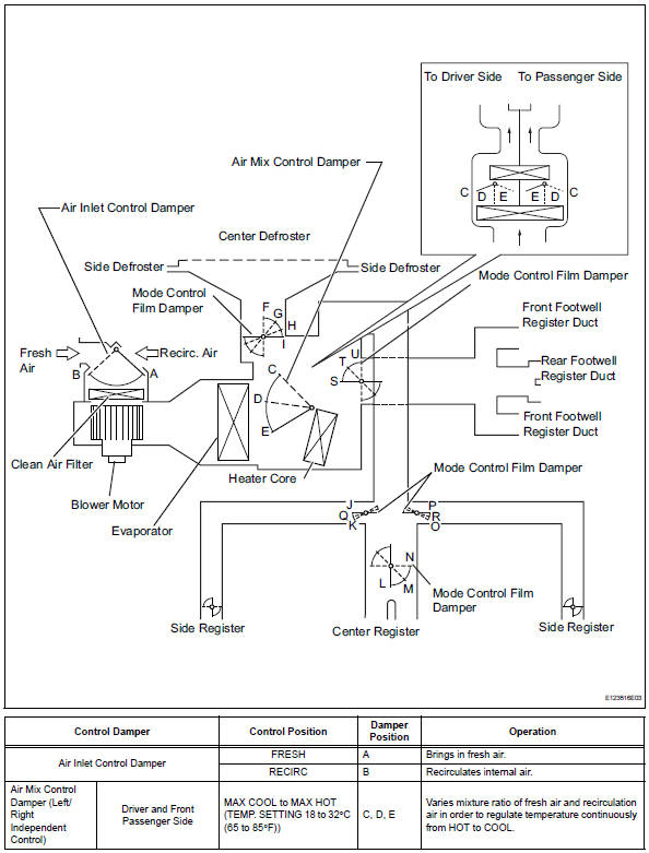
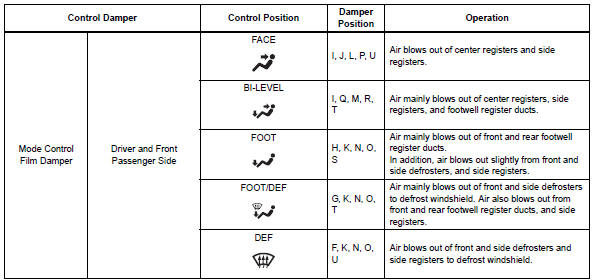
- Mode position and damper operation
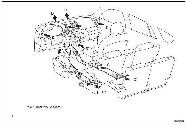
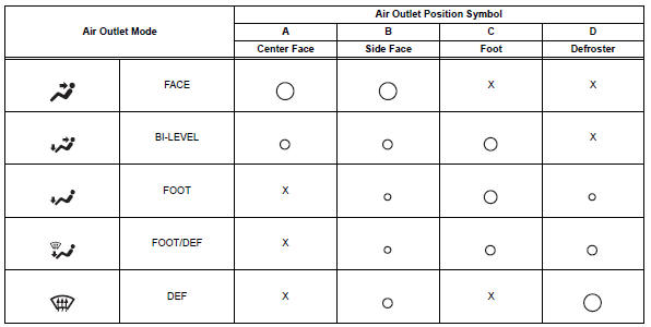
- Air outlet and airflow volume
The circle size (..) Indicates the proportion of the flow volume.
 System diagram
System diagram (2005/11-2006/01)
System diagram (2006/01- )
...
 How to proceed with troubleshooting (2005/11-2006/01)
Hint:
Use these procedures to troubleshoot the air conditioning
system.
*: Use the intelligent tester.
Vehicle brought to workshop
Customer problem analysis and symptom check
...
Other materials:
Front passenger side seat belt warning light malfunction
Description
When the ignition switch is on, the center airbag sensor transmits front seat
inner belt status signals to
the combination meter through the can bus line. If the front passenger seat belt
is not fastened, the
heater control panel (automatic a/c) or clock (manual a/c) blinks the fr ...
Engine compartment
Engine coolant reservoir
Engine oil filler cap
Battery
Brake fluid reservoir
Fuse box
Radiator
Condenser
Electric cooling fans
Engine oil level dipstick
Washer fluid tank
Engine oil
With the engine at operating temperature and turned off, check the oil
level on the dips ...
Compressor circuit
Description
When the a/c switch is turned on, the magnetic clutch on signal is sent from
the air conditioning
amplifier. Then the mg clt relay turns on to operate the magnetic clutch.
Wiring diagram
Inspection procedure
Inspection procedure
Perform active test by intelligent tester (a ...
