Toyota RAV4 (XA40) 2013-2018 Service Manual: Starter relay circuit high
![]()
Description
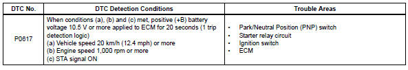
While the engine is being cranked, the positive battery voltage is applied to terminal sta of the ecm. If the ecm detects the starter control (sta) signal while the vehicle is being driven, it determines that there is a malfunction in the sta circuit. The ecm then illuminates the mil and sets the dtc.
This monitor runs when the vehicle is driven at 20 km/h (12.4 Mph) for over 20 seconds.
Monitor strategy
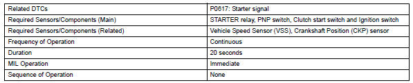
Typical enabling conditions
Typical malfunction thresholds
![]()
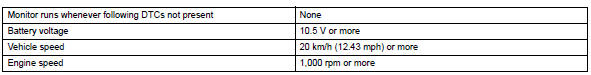
Wiring diagram
Inspection procedure
Hint:
- The following troubleshooting flowchart is based on the premise that the
engine is cranked normally.
If the engine will not crank, proceed to the problem symptoms table (see page es-24).
- Read freeze frame data using the intelligent tester. Freeze frame data records the engine condition when malfunctions are detected. When troubleshooting, freeze frame data can help determine if the vehicle was moving or stationary, if the engine was warmed up or not, if the air-fuel ratio was lean or rich, and other data from the time the malfunction occurred.
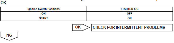
- Read value using intelligent tester (starter signal)
- Connect the intelligent tester to the dlc3.
- Turn the ignition switch on and turn the tester on.
- Select the following menu items: diagnosis / enhanced obd ii / data list / primary / starter sig.
- Check the value displayed on the tester when the ignition switch is turned to the on and start positions.
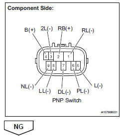
- Inspect park/neutral position switch assembly
- Disconnect the b26 pnp switch connector.
- Measure the resistance when the transmission gear selector lever is moved to each position.
Standard resistance 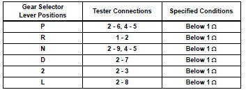
- Reconnect the pnp switch connector.

- Replace park/neutral position switch assembly

- Read value using intelligent tester (starter signal)
- Connect the intelligent tester to the dlc3.
- Turn the ignition switch on and turn the tester on.
- Select the following menu items: diagnosis / enhanced obd ii / data list / primary / starter sig.
- Check the value displayed on the tester when the ignition switch is turned to the on and start positions.
![]()


- Inspect ignition or starter switch assembly
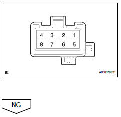
- Disconnect the e3 ignition switch connector.
- Check the resistance.
Standard resistance 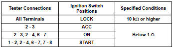
- Reconnect the ignition switch connector.
- Replace ignition or starter switch assembly

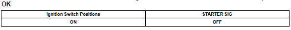
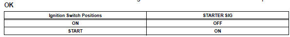
- Read value using intelligent tester (starter signal)
- Connect the intelligent tester to the dlc3.
- Turn the ignition switch on and turn the tester on.
- Select the following menu items: diagnosis / enhanced obd ii / data list / primary / starter sig.
- Check the value displayed on the tester when the ignition switch is turned to the on and start positions.


- Repair or replace harness or connector (pnp switch - sta terminal of ecm)

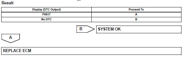
- Check whether dtc output recurs
- Connect the intelligent tester to the dlc3.
- Turn the ignition switch on.
- Turn the tester on.
- Clear dtcs (see page es-35).
- Drive the vehicle at more than 20 km/h (12.43 Mph) for over 20 seconds.
- Select the following menu items: diagnosis / enhanced obd ii / dtc info / current codes.
- Read dtcs.
 Internal control module random access memory (ram) error
Description
The ecm continuously monitors its own internal memory status, internal
circuits, and output signals
transmitted to the throttle actuator. This self-check ensures that the ecm is
...
 Vin not programmed or mismatch - ecm / pcm
Description
Dtc p0630 is set when the vehicle identification number (vin) is not stored
in the engine control module
(ecm) or the input vin is incorrect. Input the vin with the intelligent tester. ...
Other materials:
Inspection
Inspect water pump assembly
Visually check the drain hole for coolant leakage.
If leakage is found, replace the water pump
assembly.
Turn the pulley, and then check that the water pump
bearing moves smoothly without making a "click"
noise.
If it does not move s ...
Open in stop light switch circuit
Description
The skid control ecu detects the brake operating conditions through a signal
transmitted by the stop light
switch. The skid control ecu incorporates an open circuit detection circuit.
This dtc is set under either of
the following conditions:
An open is detected in the stop lig ...
Removal and installation of fuel control
parts
Place for removing and installing fuel
system parts
Work in a location with good air ventilation that
does not have welders, grinders, drills, electric
motors, stoves, or any other ignition sources.
Never work in a pit or near a pit as vaporized
fuel will collect in those places.
...
