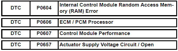
Toyota RAV4 (XA40) 2013-2018 Service Manual: Internal control module random access memory (ram) error
Description
The ecm continuously monitors its own internal memory status, internal circuits, and output signals transmitted to the throttle actuator. This self-check ensures that the ecm is functioning properly. If any malfunction is detected, the ecm sets the appropriate dtc and illuminates the mil.
The ecm memory status is diagnosed by internal mirroring of the main cpu and the sub cpu to detect random access memory (ram) errors. The two cpus also perform continuous mutual monitoring. The ecm illuminates the mil and sets a dtc if: 1) outputs from the two cpus are different or deviate from the standards, 2) the signals sent to the throttle actuator deviate from the standards, 3) a malfunction is found in the throttle actuator supply voltage, and 4) any other ecm malfunction is found.
Monitor strategy
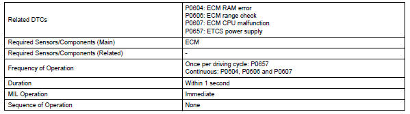
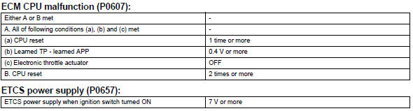
Typical enabling conditions
![]()
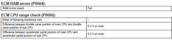
Typical malfunction thresholds
Inspection procedure
Read freeze frame data using the intelligent tester. Freeze frame data records the engine condition when malfunctions are detected. When troubleshooting, freeze frame data can help determine if the vehicle was moving or stationary, if the engine was warmed up or not, if the air-fuel ratio was lean or rich, and other data from the time the malfunction occurred.
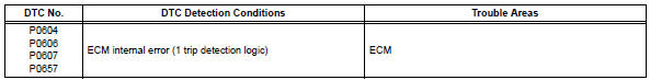
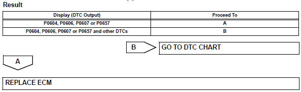
- Check any other dtcs output (in addition to dtc p0604, p0606, p0607 or p0657)
- Connect the intelligent tester to the dlc3.
- Turn the ignition switch on.
- Turn the tester on.
- Select the following menu items: diagnosis / enhanced obd ii / dtc info / current codes.
- Read dtcs.
 System voltage
Description
The battery supplies electricity to the ecm even when the ignition switch is
in the off position. This
power allows the ecm to store data such as dtc history, freeze frame data and ...
 Starter relay circuit high
Description
While the engine is being cranked, the positive battery voltage is applied to
terminal sta of the ecm. If
the ecm detects the starter control (sta) signal while the vehicle is bein ...
Other materials:
Types of child restraints
Child restraint systems are classified into the following 3 types
according to the age and size of the child:
Rear facing „o infant seat/convertible
seat
Forward facing „o convertible
seat
Booster seat
Selecting an appropriate child restraint system
Use a child restraint ...
Transmission fluid temperature sensor "A" performance
Description
Refer to dtc p0710 (see page ax-46).
Monitor description
This dtc indicates that there is a problem with output from the atf
temperature sensor and that the
sensor itself is defective. The atf temperature sensor converts the atf
temperature to an electrical
resistance v ...
Before driving
Observe the following
before starting off in the
vehicle to ensure safety of
driving.
Installing floor mats
Use only floor mats designed
specifically for vehicles of the
same model and model year as
your vehicle. Fix them securely
in place onto the carpet.
1. Insert the retaining hooks
(clips) into ...
