Toyota RAV4 (XA40) 2013-2018 Service Manual: System voltage
![]()
Description
The battery supplies electricity to the ecm even when the ignition switch is in the off position. This power allows the ecm to store data such as dtc history, freeze frame data and fuel trim values. If the battery voltage falls below a minimum level, the memory is cleared and the ecm determines that there is a malfunction in the power supply circuit. When the engine is next started, the ecm illuminates the mil and sets the dtc.
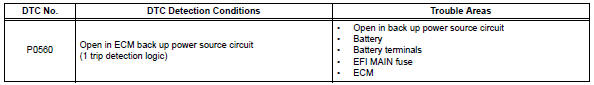
Hint:
If dtc p0560 is set, the ecm does not store other dtcs or the data stored in the ecm are partly erased.
Monitor strategy
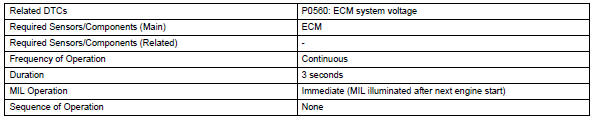
Typical enabling conditions
![]()
Typical malfunction thresholds
![]()
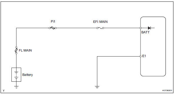
Wiring diagram
Inspection procedure
Hint:
Read freeze frame data using the intelligent tester. Freeze frame data records the engine condition when malfunctions are detected. When troubleshooting, freeze frame data can help determine if the vehicle was moving or stationary, if the engine was warmed up or not, if the air-fuel ratio was lean or rich, and other data from the time the malfunction occurred.
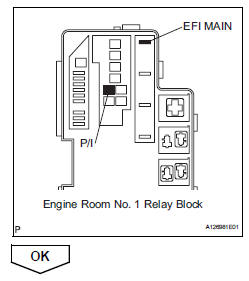
- Check fuse (efi main and p/i)
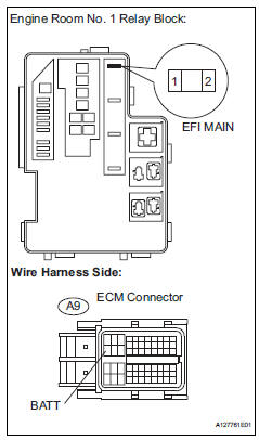
- Remove the efi main fuse and p/i fuse from the engine room no. 1 Relay block.
- Measure the resistance of the efi main fuse and p/i fuse.
Standard resistance:
below 1 
- Reinstall the efi main fuse and p/i fuse.
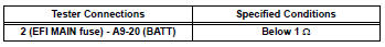
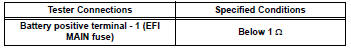
- Check harness and connector (ecm - efi main fuse, efi main fuse - battery)
- Check the harness and the connector between the efi main fuse and ecm.
- Remove the efi main fuse from the engine no. 1 Room relay block.
- Disconnect the a9 ecm connector.
- Measure the resistance.
Standard resistance (check for open)
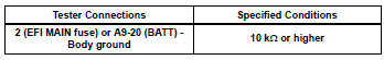
Standard resistance (check for short)
- Reconnect the ecm connector.
- Reinstall the efi main fuse.
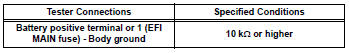
- Check the harness and the connector between the efi main fuse and battery.
- Remove the efi main fuse from the engine room no. 1 Relay block.
- Disconnect the positive battery terminal.
- Check the resistance.
Standard resistance (check for open)
Standard resistance (check for short)
- Reconnect the positive battery terminal.
- Reinstall the efi main fuse.

- Inspect battery
- Check that the battery is not depleted.
Ok: battery is not depleted


- Check battery terminal
- Check that the battery terminals are not loose or corroded.
Ok: battery terminals are not loose or corroded


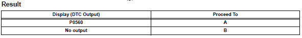
- Check whether dtc output recurs
- Connect the intelligent tester to the dlc3.
- Turn the ignition switch on and turn the tester on.
- Clear dtcs (see page es-35).
- turn the ignition switch off and turn the tester off.
- Start the engine and turn the tester on.
- Select the following menu items: diagnosis / enhanced obd ii / dtc info / current codes.
- Read dtcs.
 Battery temperature sensor circuit
Description
The battery temperature sensor installed on the battery current sensor
detects battery temperature.
A thermistor is integrated into the battery temperature sensor, and the
...
 Internal control module random access memory (ram) error
Description
The ecm continuously monitors its own internal memory status, internal
circuits, and output signals
transmitted to the throttle actuator. This self-check ensures that the ecm is
...
Other materials:
Power windows
Opening and closing the
power windows
The power windows can be
opened and closed using the
switches.
Operating the switch moves the
side windows as follows:
Closing
One-touch closing*
Opening
One-touch opening*
*: To stop the side window partway,
operate the switch in the opposite
direction. ...
Terminals of ecu
Skid control ecu
Hint:
*1: W/ 16-inch disc
*2: W/ downhill assist control
*3: For 2wd (w/ auto lsd)
Check skid control ecu
Disconnect the a19 ecu connector.
Measure the voltage and resistance of the wire
harness side connector.
Hint:
The voltage cannot be measured ...
Adjusting the open position
of the back door
(vehicles with power back
door)
The open position of the power
back door can be adjusted.
1. Stop the back door in the
desirable position.
2. Press and hold the power
back door switch on the back
door for approximately 2 seconds.
When the settings are completed,
the buzzer sounds 4 times.
When opening the back door the
next time ...
