Toyota RAV4 (XA40) 2013-2018 Service Manual: Battery temperature sensor circuit
Description
The battery temperature sensor installed on the battery current sensor detects battery temperature.
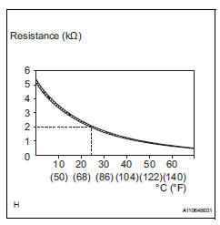
A thermistor is integrated into the battery temperature sensor, and the resistance in the battery temperature sensor changes according to the battery temperature.
The resistance of the thermistor in the battery temperature sensor decreases as the battery temperature increases. The resistance increases as the temperature decreases.
The battery temperature sensor is connected to the ecm. The ecm supplies 5 v from the thb terminal to the battery temperature sensor through resistor r.
The battery temperature sensor and resistor r are connected in series. This results in fluctuations in the voltage supplied from the thb terminal when the resistance changes according to the battery temperature.
The ecm determines the battery temperature according to fluctuations in voltage. When the battery temperature is high, the ecm determines to reduce the amount of current supplied from the generator in order to protect the battery.
Wiring diagram
Refer to dtc p1550 (see page es-262)
Inspection procedure
- Inspect battery current sensor
- Disconnect the b29 battery current sensor connector.
- Measure the resistance.
Standard resistance 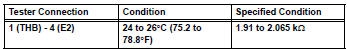
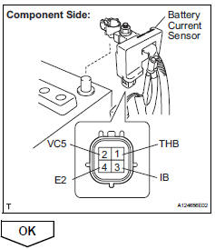
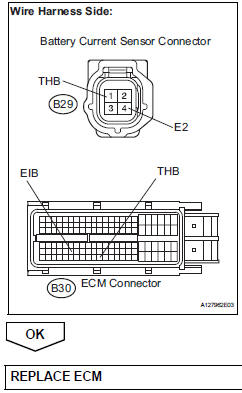
- Check harness and connector (battery current sensor - ecm)
- Disconnect the b29 battery current sensor connector.
- Disconnect the b30 ecm connectors.
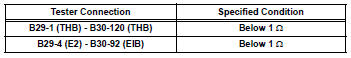
- Measure the resistance of the wire harness side connectors.
Standard resistance (check for open)
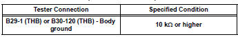
Standard resistance (check for short)
 Cold start
Description
The electronic throttle control system (etcs) controls the engine idling
speed. The etcs operates the
throttle actuator to open and close the throttle valve, and adjusts the intake ...
 System voltage
Description
The battery supplies electricity to the ecm even when the ignition switch is
in the off position. This
power allows the ecm to store data such as dtc history, freeze frame data and ...
Other materials:
Front suspension lower no. 1 Arm
Components
Removal
Remove front wheel
Remove hood sub-assembly
Remove the hood (see page ed-4).
Suspend engine assembly
Install the no. 1 And no. 2 Engine hangers with the
bolts as shown in the illustration.
Torque: 38 n*m (387 kgf*cm, 28 ft.*Lbf)
parts no.
...
Changing the display
The multi-information display is
operated using the meter control
switches.
Scroll the screen*/switch the
display*/move the cursor
Press: Enter/Set
Press and hold: Reset/Display
customizable items
Return to the previous screen
Call sending/receiving and
history display (if equipped)
Linke ...
Operating a usb memory
Connecting a usb memory enables you to enjoy music from the
vehicle speakers.
Connecting a usb memory
Open the cover and connect
a usb memory.
Turn on the power of the usb
memory if it is not turned on.
Press the “media” button repeatedly until “usb” is displayed.
Cont ...
