Toyota RAV4 (XA40) 2013-2018 Service Manual: Automatic transaxle assembly
Components
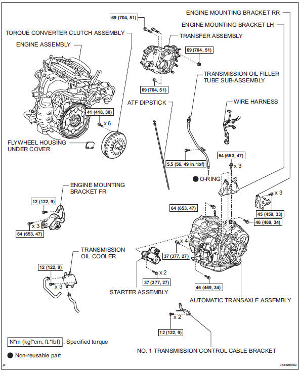
Removal
- Remove engine assembly with transaxle
- Remove the engine with transaxle (see page em- 98).
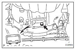
- Drain automatic transaxle fluid
- Remove the drain plug and gasket, and drain atf.
- Install a new gasket and the drain plug.
Torque: 47 n*m (479 kgf*cm, 35 ft.*Lbf)
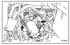
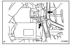
- Remove starter assembly
- Disconnect the starter connector.
- Open the terminal cap, and remove the nut and disconnect the starter wire.
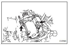
- Remove the 2 bolts and starter.
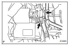
- Disconnect wire harness
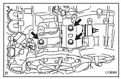
- Disconnect the park/neutral position switch connector.
- Disconnect the transaxle wire connector.
- Disconnect the 2 speed sensor connectors.
- Disconnect the wire harness clamps.
- Remove transmission oil cooler
- Remove the oil cooler (see page ax-127).
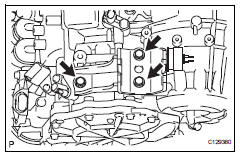
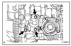
- Remove engine mounting bracket rr
- Remove the 3 bolts and mounting bracket.
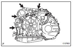
- Remove engine mounting bracket fr
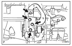
- Remove the 4 bolts and mounting bracket.
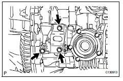
- Remove engine mounting bracket lh
- Remove the 3 bolts and mounting bracket.
- Remove transfer assembly
- Remove the transfer (see page tf-59).
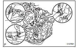
- Remove automatic transaxle assembly
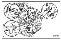
- Remove the flywheel housing under cover
- Turn the crankshaft to gain access and remove the 6 bolts while holding the crankshaft pulley bolt with a wrench.
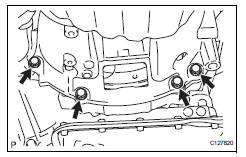
- Remove the 4 lower side mounting bolts.
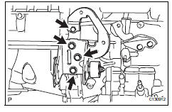
- Remove the 5 upper side mounting bolts.
- Separate and remove the automatic transaxle.
- Remove transmission oil filler tube subassembly
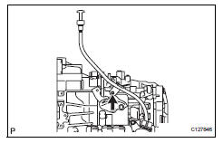
- Remove the atf dipstick.
- Remove the bolt and oil filler tube.
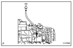
- Remove no. 1 Transmission control cable bracket
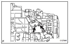
- Remove the 2 bolts and cable bracket.
- Remove torque converter clutch assembly
Installation
- Inspect torque converter clutch assembly
- Inspect the torque converter (see page ax-153).
- Install torque converter clutch assembly
- Install the torque converter clutch to the automatic transaxle.
- Using a vernier caliper, measure dimension a between the transaxle and the end surface of the drive plate.
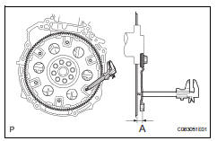
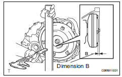
- Using a vernier caliper and straightedge, measure the dimension b shown in the illustration and check that b is greater than a.
Standard dimension: a + 1.0 Mm (0.039 In.) Or more
- Install no. 1 Transmission control cable bracket
- Install the cable bracket with the 2 bolts.
Torque: 12 n*m (122 kgf*cm, 9 ft.*Lbf)
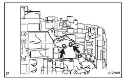
- Install transmission oil filler tube subassembly
- Install the filler tube with the bolt.
- Install the filler tube with the bolt.
Torque: 5.5 N*m (56 kgf*cm, 49 in.*Lbf)
- Install the atf dipstick.
- Install automatic transaxle assembly
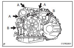
- Install the automatic transaxle with the 5 upper side mounting bolts to the engine.
Torque: 64 n*m (653 kgf*cm, 47 ft.*Lbf) for bolt a 46 n*m (469 kgf*cm, 34 ft.*Lbf) for bolt b
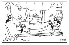
- Install the 4 lower side mounting bolts.
Torque: 37 n*m (377 kgf*cm, 27 ft.*Lbf)
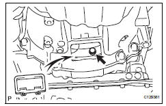
- Install the 6 torque converter clutch mounting bolts.
Torque: 41 n*m (418 kgf*cm, 30 ft.*Lbf)
Hint:
First install the green colored bolt and then the 5 bolts.
- Install the flywheel housing under cover.
- Install transfer assembly
- Install the transfer (see page tf-75).
- Install engine mounting bracket lh
- Install the mounting bracket with the 3 bolts.
Torque: 64 n*m (653 kgf*cm, 47 ft.*Lbf)
- Install engine mounting bracket fr
- Install the mounting bracket with the 4 bolts.
Torque: 64 n*m (653 kgf*cm, 47 ft.*Lbf) for 14 mm head bolt
Torque: 12 n*m (122 kgf*cm, 9 ft.*Lbf) for 12 mm head bolt
- Install engine mounting bracket rr
- Install the mounting bracket with the 3 bolts.
Torque: 45 n*m (459 kgf*cm, 33 ft.*Lbf)
- Install transmission oil cooler
- Install the oil cooler (see page ax-127).
- Connect wire harness
- Connect the wire harness clamps.
- Connect the 2 speed sensor connectors.
- Connect the transaxle wire connector.
- Connect the park/neutral position switch connector.
- Install starter assembly
- Install the starter with the 2 bolts.
Torque: 37 n*m (377 kgf*cm, 27 ft.*Lbf)
- Connect the starter wire with the nut.
Torque: 13 n*m (133 kgf*cm, 10 ft.*Lbf)
- Connect the starter connector.
- Install the terminal nut and cover the nut with the
cap.
Torque: 9.8 N*m (100 kgf*cm, 7 in.*Lbf)
- Install engine assembly with transaxle
- Install the engine with transaxle. (See page em- 105).
- Add automatic transaxle fluid
Fluid type: toyota genuine atf ws
- Inspect automatic transaxle fluid
- Inspect the automatic transaxle fluid (see page ax- 102).
- Perform reset memory
- Perform the reset memory procedures (a/t initialization) (see page ax-18).
 Differential oil seal
Components
Replacement
Replace transaxle housing oil seal lh
Drain the automatic transaxle fluid.
Remove the drain plug and gasket, and drain
atf.
Install a new gasket and ...
 Torque converter and drive plate
Inspection
Inspect torque converter clutch assembly
Inspect the one-way clutch.
Install sst to the inner race of the one-way
clutch.
Sst 09350-32014 (09351-32010)
Set sst s ...
Other materials:
Shift solenoid "d" control circuit
Description
Shifting from 1st to o/d is performed in combination with the on and off
operation of the shift solenoid
valves sl1 and sl2, which are controlled by the ecm. If an open or short circuit
occurs in any of the shift
solenoid valves, the ecm controls the remaining normal shift sol ...
Brake switch "A" / "B" correlation
Description
The stop light switch is a duplex system that transmits two signals: stp and
st1-. These two signals are
used by the ecm to monitor whether or not the brake system is working properly.
If the signals, which
indicate the brake pedal is being depressed and released, are detected ...
Vsc warning light does not come on
Description
Refer to the description of "vsc warning light remains on" (see page bc-139).
Wiring diagram
Refer to the vsc warning light circuit (see page bc-140).
Inspection procedure
Notice:
When replacing the abs and traction actuator, perform the zero point
calibration (see page ...
