Toyota RAV4 (XA40) 2013-2018 Service Manual: Disassembly
- Remove radiator grille sub-assembly
- Remove the 4 bolts and 4 nuts.
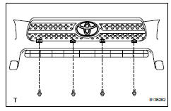
- Detach the 6 claws and remove the radiator grille.
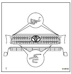
- Remove no. 1 Radiator grille lower
- Detach the 18 claws and remove the radiator grille.
- Remove no. 2 Radiator grille lower
- Detach the 16 claws and remove the radiator grille.
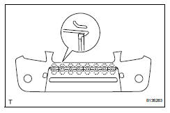
- Remove front bumper arm hole cover lh
- Detach the 2 claws and disconnect the arm hole cover.
- Remove the hook and bumper arm hole cover.
- Remove front bumper arm hole cover rh
- Use the same procedures described for the lh side.
- Remove fog light assembly lh
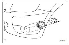
- Remove the screw and fog light.
- Remove the 3 bolts and fog light mounting bracket.
- Remove fog light assembly rh
Hint:
Use the same procedures described for the lh side.
- Remove front bumper hole cover lh (w/o fog light)
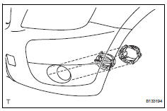
- Remove the 3 bolts, bumper hole cover and fog light mounting bracket.
- Remove front bumper hole cover rh (w/o fog light)
Hint:
Use the same procedures described for the lh side.
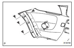
- Remove front bumper extension lh (for wide body)
- Detach the 7 outside moulding retainers and remove the extension lh.
Notice:
- If reusing the extension, take care not to damage the extension.
- Be careful not to damage the vehicle body.
- Remove front bumper extension rh (for wide body)
Hint:
Use the same procedures described for the lh side.
 Removal
Disconnect cable from negative battery
terminal
Caution:
Wait at least 90 seconds after disconnecting the
cable from the negative (-) battery terminal to
prevent airbag and seat belt preten ...
 Reassembly
V
Attach the 7 outside moulding retainers to install the
extension.
Install front bumper extension rh (for wide
body)
Hint:
Use the same procedures described for the lh side ...
Other materials:
Security indicator light circuit
Description
When the transponder key is registered, the transponder key ecu indicates the
key registration condition
by lighting up, blinking or turning off the security indicator.
Wiring diagram
Inspection procedure
Perform active test by intelligent tester (security indicator light)
...
Diagnostic trouble code chart (2006/01- )
Hint:
When the air conditioning system functions properly, dtc
b1400/00 is output.
Hint:
*1: Dtc b1422/22 (compressor lock sensor circuit) is
indicated only for a currently occurring malfunction for 2grfe.
*2: Compressor and pulley for 2az-fe, compressor and
magnetic clutch for 2gr-fe ...
Making a phone call
To enter the “phone” mode, press the off-hook switch.
Making a phone call
Dialing by inputting a name
Speed dialing
Dialing by entering the number
Dialing from call histories
Receiving a phone call
Answering the phone
Refusing the call
Operations during a call
Transfer ...
