Toyota RAV4 (XA40) 2013-2018 Service Manual: Reassembly
- V
- Attach the 7 outside moulding retainers to install the extension.
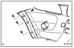
- Install front bumper extension rh (for wide body)
Hint:
Use the same procedures described for the lh side.
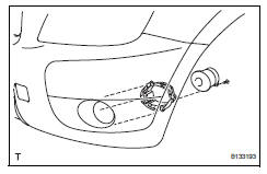
- Install front bumper hole cover lh (w/o fog light)
- Install the bumper hole cover with the fog light mounting bracket and 3 bolts.
- Install front bumper hole cover rh (w/o fog light)
Hint:
Use the same procedures described for the lh side.
- Install fog light assembly lh
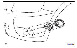
- Install the fog light mounting bracket with the 3 bolts.
- Install the fog light with the screw.
- Install fog light assembly rh
Hint:
Use the same procedures described for the lh side.
- Install front bumper arm hole cover lh
- Install the hook.
- Attach the 2 claws and install the hole cover.
- Install front bumper arm hole cover rh
Hint:
Use the same procedures described for the lh side.
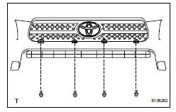
- Install no. 2 Radiator grille lower
- Install the radiator grille and attach the 16 claws.
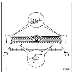
- Install no. 1 Radiator grille lower
- Install the radiator grille and attach the 18 claws.
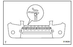
- Install radiator grille sub-assembly
- Install the radiator grille with the 6 claws.
- Install the 4 bolts and 4 nuts.
 Disassembly
Remove radiator grille sub-assembly
Remove the 4 bolts and 4 nuts.
Detach the 6 claws and remove the radiator grille.
Remove no. 1 Radiator grille lower
Detach the 1 ...
 Installation
Install front bumper side retainer lh
Install the clip and bumper side retainer.
Install the bolt.
Torque: 6.0 N*m (61 kgf*cm, 53 in.*Lbf)
Install front bumper side retainer rh
...
Other materials:
No signal from transmitter id
Description
The tire pressure warning valve and transmitter constantly sends radio waves
to the tire pressure warning
ecu.
Under the following conditions, the tire pressure warning antenna and receiver
is unable to receive the
signals from the tire pressure warning valve and transmitte ...
Removal
Remove radiator support opening cover
Remove front wheel rh
Remove front fender apron rh
Remove front suspension member
reinforcement rh
Remove the 4 bolts and reinforcement rh.
Remove fan and generator v belt
Using sst and 19 mm socket wrench, loosen the vribbed
belt ...
Mass air flow circuit range / performance problem
Description
Refer to dtc p0100 (see page es-86).
Monitor description
The maf meter is a sensor that measures the amount of air flowing through the
throttle valve. The ecm
uses this information to determine the fuel injection time and to provide an
appropriate air-fuel ratio. Inside
...
