Toyota RAV4 (XA40) 2013-2018 Service Manual: Installation
- Install front bumper side retainer lh
- Install the clip and bumper side retainer.
- Install the bolt.
Torque: 6.0 N*m (61 kgf*cm, 53 in.*Lbf)
- Install front bumper side retainer rh
Hint:
Use the same procedures described for the lh side.
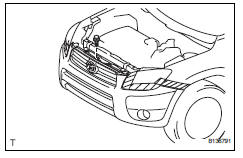
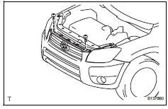
- Install front bumper reinforcement
- Install the reinforcement with the 8 bolts.
Torque: 70 n*m (713 kgf*cm, 51 ft.*Lbf)
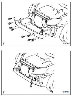
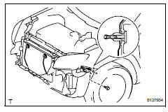
- Install the wire harness and attach the 5 claws.
- Install front bumper retainer
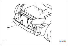
- Install the bolt with the retainer.
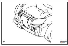
- Install no. 2 Front bumper energy absorber
- Install the absorber.
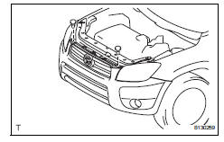
- Install front bumper cover
- Put protective tape under the front fender and headlight.
- Install the 4 clips.
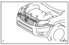
- Install the hood cushion center.
- W/ fog light: connect the 2 fog light connectors.
- Attach the 4 claws to install the bumper cover.
- Install the 8 screws.
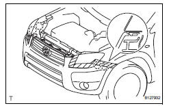
- Install radiator support opening cover
- Install the 2 clips.
- Install radiator grille protector
- Install the 2 radiator grille protectors.
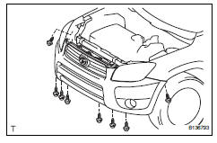
- Install front fender liner lh
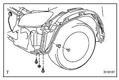
- Install the fender liner with the fender liner retainer.
- W/ splash shield: install the front fender splash shield lh.
- Install the screw, nut and bolt.
- Install front fender liner rh
Hint:
Use the same procedures described for the lh side.
- Connect cable to negative battery terminal
 Reassembly
V
Attach the 7 outside moulding retainers to install the
extension.
Install front bumper extension rh (for wide
body)
Hint:
Use the same procedures described for the lh side ...
 Rear bumper
Components
Removal
Remove rear bumper cover
Remove the 9 screws and 7 clips.
Put protective tape under the quarter panel.
Detach the 12 claws and remove the bumper cover.
...
Other materials:
Removal
Disconnect cable from negative battery
terminal
Caution:
Wait at least 90 seconds after disconnecting the
cable from the negative (-) battery terminal to
prevent airbag and seat belt pretensioner activation.
Remove radiator support opening cover
Remove front wheel rh
Remove no. 1 ...
Evaporative emission control system incorrect purge flow
Dtc summary
Description
The description can be found in the evap (evaporative emission) system (see
page es-335).
Inspection procedure
Refer to the evap system (see page es-340).
Monitor description
The two monitors, key-off and purge flow, are used to detect malfunctions
relating ...
Vsc warning light does not come on
Description
Refer to the description of "vsc warning light remains on" (see page bc-139).
Wiring diagram
Refer to the vsc warning light circuit (see page bc-140).
Inspection procedure
Notice:
When replacing the abs and traction actuator, perform the zero point
calibration (see page ...
