Toyota RAV4 (XA40) 2013-2018 Service Manual: Calibration
- Description
- After replacing components relating to the vsc or performing "front wheel alignment adjustment", clear and read the sensor calibration data.
- Follow the chart to perform calibration.
- Clear zero point calibration data (when using intelligent tester)
- Clear the zero point calibration data.
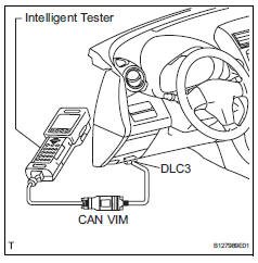
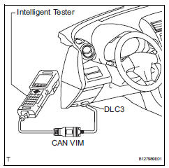
- Connect the intelligent tester (with can vim) to the dlc3.
- Turn the ignition switch on.
- Operate the intelligent tester to erase the codes (select "reset memory").
Hint:
Refer to the intelligent tester operator's manual for further details.
- Using the intelligent tester, perform the zero point calibration of the yaw rate and deceleration sensor.
Caution:
If the ignition switch is turned on for more than 15 seconds with the shift lever in the p position after zero point of the yaw rate and acceleration sensor has been cleared, only the zero point of the yaw rate sensor will be stored. If the vehicle is driven under this condition, the skid control ecu will recognize that zero point calibration of the acceleration sensor is not completed and will indicate that there is a malfunction in the vsc system using the indicator light.
- Preform zero point calibration of yaw rate and deceleration sensor (when using intelligent tester)
Notice:
- While obtaining the zero point, do not vibrate the vehicle by tilting, moving or shaking it and keep it stationary. (Do not start the engine.)
- Perform this on a level surface (with an inclination of less than 1°).
- Procedures for test mode.
- Check that the shift lever is in the p position and apply the parking brake.
Notice:
Dtcs c1210/36 and c1336/39 will be recorded if the shift lever is not the p position (see page bc-88).
- Connect the intelligent tester (with can vim) to the dlc3.
- Turn the ignition switch on.
- Set the intelligent tester to test mode (select "test mode").
Hint:
Refer to the intelligent tester operator's manual for further details.
- Obtain the zero point of the yaw rate and deceleration sensor.
- Keep the vehicle stationary on a level surface for 2 seconds or more.
- Check that the vsc warning light blinks as shown in the illustration.
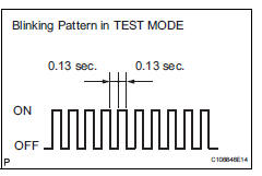
Hint:
- If the vsc warning light does not blink, perform the zero point calibration again.
- The zero point calibration is performed only once after the system enters test mode.
- Calibration cannot be performed again until the stored data is cleared once.
- Turn the ignition switch off.
- Clear zero point calibration data (when not using intelligent tester)
- Clear the zero point calibration data.
- Turn the ignition switch on.
- The warning light and indicator light come on for 3 seconds to indicate that the initial check is completed.
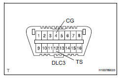
- Using sst, connect and disconnect terminals 12 (ts) and 4 (cg) of the dlc3 4 times or more within 8 seconds.
Sst 09843-18040
- Check that the vsc warning light comes on.
- Remove sst from the terminals of the dlc3.
- Using a check wire, perform the zero point calibration of the yaw rate and deceleration sensor.
Caution:
If the ignition switch is turned on for more than 15 seconds with the shift lever in the p position after zero point of the yaw rate and acceleration sensor has been cleared, only the zero point of the yaw rate sensor will be stored. If the vehicle is driven under this condition, the skid control ecu will recognize that zero point calibration of the acceleration sensor is not completed and will indicate that there is a malfunction in the vsc system using the indicator light.
- Perform zero point calibration of yaw rate and deceleration sensor (when not using intelligent tester)
Notice:
- While obtaining the zero point, do not vibrate the vehicle by tilting, moving or shaking it and keep it stationary. (Do not start the engine.)
- Perform this on a level surface (with an inclination of less than 1°).
- Procedures for test mode.
- Turn the ignition switch off
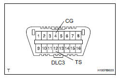
- Using sst, connect terminals 12 (ts) and 4 (cg) of the dlc3.
Sst 09843-18040
- Check that the shift lever is in the p position and apply the parking brake.
Notice:
Dtcs c1210/36 and c1336/39 will be recorded if the shift lever is not the p position (see page bc-88).
- Obtain the zero point of the yaw rate and deceleration sensor.
- Turn the ignition switch on.
- Keep the vehicle stationary on a level surface for 2 seconds or more.
- Check that the vsc warning light blinks as shown in the illustration.
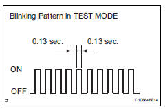
Hint:
- If the vsc warning light does not blink, perform the zero point calibration again.
- The zero point calibration is performed only once after the system enters test mode.
- Calibration cannot be performed again until the stored data is cleared once.
- Turn the ignition switch off.
 Check for intermittent problems
Check for intermittent problems
Hint:
A momentary interruption (open circuit) in the connectors
and/or wire harness between the sensors and ecus can
be detected by using the ecu data list fun ...
 Test mode procedure
Hint:
By switching the skid control ecu from normal mode to
test mode, abnormality detection sensitivity is enhanced
and troubleshooting can be conducted efficiently.
Perform a sensor check ...
Other materials:
Can bus line
Description
When any dtc for the can communication system is output, first measure the
resistance between the
terminals of the dlc3 to specify the trouble area, and check that there is not a
short in the can main wire,
between the main wire, to +b, or to gnd.
Wiring diagram
Inspecti ...
Cooling system
On-vehicle inspection
Check cooling system for leaks
Remove the radiator reservoir cap.
Caution:
To avoid the danger of being burned, do not
remove the radiator reservoir cap while the
engine and radiator are still hot. Thermal
expansion will cause hot engine coolant and
steam to b ...
Manual shifting test
Manual shifting test
Hint:
Through this test, it can be determined whether the
trouble occurs in the electrical circuit or if it is a
mechanical problem in the transaxle.
If any abnormalities are found in the following test, the
problem is in the transaxle itself.
Disconnect ...
