Toyota RAV4 (XA40) 2013-2018 Service Manual: Low battery positive voltage
![]()
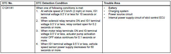
Description
When there is an abnormality in the power supply circuit of the brake actuator (skid control ecu), the skid control ecu sets a dtc and the operation is prohibited by the fail-safe function. This dtc is set when the voltage supplied to terminal ig1 is outside the dtc detection threshold, due to abnormalities of the battery, power source circuits or charging circuits such as the alternator circuit.
The fail-safe function is canceled when the voltage to terminal ig1 returns to normal.
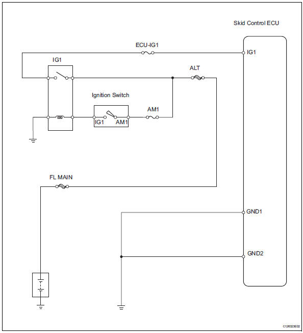
Wiring diagram
Inspection procedure
- Inspect fuse (ecu-ig1)
- Remove the ecu-ig1 fuse from the instrument panel junction block.
- Measure the resistance of the fuse.
Standard resistance:
below 1 


- Inspect battery
- Check the battery voltage.
Standard voltage: 11 to 14 v

- Check wire harness (skid control ecu - battery)
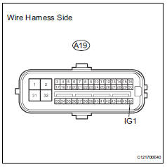
- Disconnect the a19 ecu connector.
- Measure the voltage of the wire harness side connector.
Standard voltage 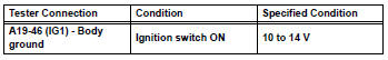

- Check wire harness (skid control ecu - body ground)
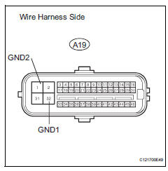
- Disconnect the a19 ecu connector.
- Measure the resistance of the wire harness side connector.
Standard resistance 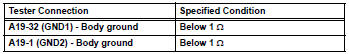

- Reconfirm dtc
- Clear the dtc (see page bc-47).
- Drive the vehicle at 3 km/h (2 mph) or more for several seconds.
- Check if the same dtc is output (see page bc-47).
Result 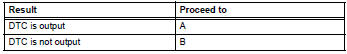

Replace abs and traction actuator assembly
 Stuck in deceleration sensor
Description
The skid control ecu receives signals from the yaw rate and deceleration
sensor via the can
communication system.
The yaw rate sensor has a built-in deceleration sensor and dete ...
 Master cylinder pressure sensor malfunction
Description
The master cylinder pressure sensor is connected to the skid control ecu in
the abs and traction
actuator.
Dtc c1281/81 can be detected when the master cylinder pressure sensor ...
Other materials:
Brk relay
On-vehicle inspection
Inspect brk relay
Remove the brk relay from the engine room no. 1
Relay block.
Measure the resistance of the relay.
Standard resistance
If the result is not as specified, replace the relay. ...
Installation
Install drive plate sub-assembly
Clean the 8 bolts and 8 bolt holes.
Apply adhesive to 2 or 3 threads of the 8 bolts.
Adhesive:
Toyota genuine adhesive 1342, three bond
1342 or equivalent
Using sst, hold the crankshaft.
Sst 09213-54015 (91651-60855), 09330-00021
Instal ...
Blower motor circuit
Description
The blower motor is operated by signals from the air conditioning amplifier.
Blower motor speed signals
are transmitted in accordance with changes in the duty ratio.
Wiring diagram
Inspection procedure
Perform active test by intelligent tester (blower motor)
Conne ...
