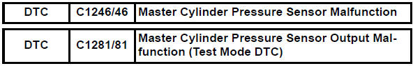
Toyota RAV4 (XA40) 2013-2018 Service Manual: Master cylinder pressure sensor malfunction
Description
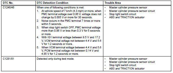
The master cylinder pressure sensor is connected to the skid control ecu in the abs and traction actuator.
Dtc c1281/81 can be detected when the master cylinder pressure sensor sends a master cylinder pressure signal or test mode ends. Dtc c1281/81 is output only in test mode.
Inspection procedure
Notice:
When replacing the abs and traction actuator, perform zero point calibration (see page bc-24).
- Read value of intelligent tester (stop light switch)
- Check the data list for proper functioning of the stop light switch.
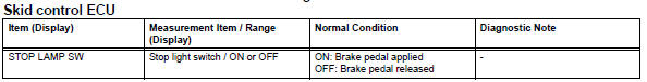
Ok: on (brake pedal is depressed) appears on the screen.

- Read value of intelligent tester (master cylinder pressure sensor)
- Check the data list for proper functioning of the master cylinder pressure sensor.
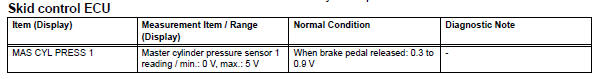
Ok: when the pedal is depressed, the sensor output voltage increases.

- Reconfirm dtc
- Clear the dtc(s) (see page bc-47).
- Drive the vehicle at a speed of 30 km/h (18 mph) or more and perform a braking test (decelerate the vehicle by depressing the brake pedal).
- Check if the same dtc(s) is recorded (see page bc-47).
Result 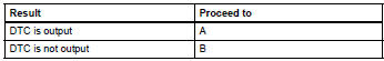

Replace abs and traction actuator assembly
 Low battery positive voltage
Description
When there is an abnormality in the power supply circuit of the brake
actuator (skid control ecu), the skid
control ecu sets a dtc and the operation is prohibited by the fail-safe ...
 Open in stop light switch circuit
Description
The skid control ecu detects the brake operating conditions through a signal
transmitted by the stop light
switch. The skid control ecu incorporates an open circuit detection circuit. ...
Other materials:
Using the radio
Power
Volume
Adjusting the frequency
Scanning for receivable stations
Am/fm mode button
Station selectors
Seeking the frequency
Displaying text message
Setting station presets
Search for the desired stations by turning the ¢Â§tune¢escroll¢¸
knob or ...
Compressor and pulley (for 2az-fe)
Components
Removal
Discharge refrigerant from
refrigeration system (see page ac-172)
Disconnect cable from negative battery
terminal
Caution:
Wait at least 90 seconds after disconnecting the
cable from the negative (-) battery terminal to
prevent airbag and seat belt pretensione ...
Installation
Hint:
Use the same procedures for the rh side and lh side.
The procedures listed below are for the lh side.
Install rear stabilizer bush
Install the 2 bushes.
Hint:
Install each bush to the outer side of the bush
stopper on each stabilizer bar.
Install each bush with ...
