Toyota RAV4 (XA40) 2013-2018 Service Manual: On-vehicle inspection
Notice:
- Perform the maf meter inspection according to the procedures below.
- Only replace the maf meter when both the long ft#1 value and maf value in the data list (with the engine stopped) are not within the normal operating range.
- Inspect mass air flow meter
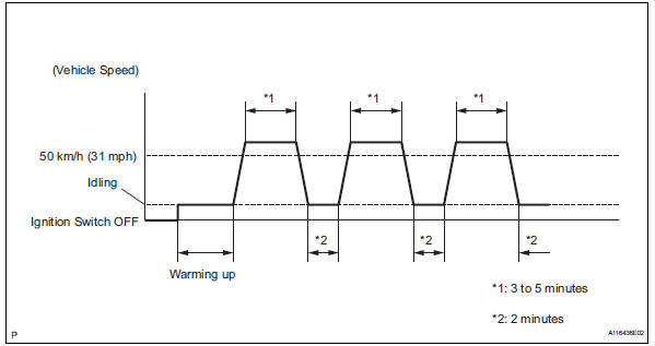
- Perform confirmation driving pattern.
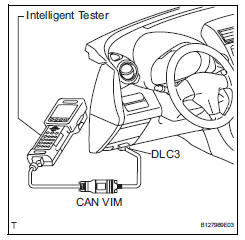
- Connect the intelligent tester to the dlc3.
- Turn the ignition switch on.
- Turn the tester on.
- Clear the dtcs (see page es-35).
- Start the engine and warm it up with all accessory switches off until the engine coolant temperature is 75°c (167°f) or more.
- Drive the vehicle at 50 km/h (31 mph) or more for 3 to 5 minutes*1.
- Allow the engine to idle for 2 minutes*2.
- Perform steps *1 and *2 at least 3 times.
- Read the value using the intelligent tester (long ft#1).
- Select the following menu items: diagnosis / enhanced obd ii / data list / primary / long ft#1.
- Read the values displayed on the tester.
Standard value: within -15 to +15%
If the result is not within the specified range, perform the inspection below.
- Read the value using the intelligent tester (maf).
Notice:
- Turn off the engine.
- Perform the inspection with the vehicle indoors and on a level surface.
- Perform the inspection of the maf meter while it is installed to the air cleaner case (installed to the vehicle).
- During the test, do not use the exhaust air duct to perform suction on the exhaust pipe.
- Turn the ignition switch to acc.
- Turn the ignition switch on (do not run the engine).
- Turn the tester on.
- Select the following menu items: diagnosis / enhanced obd ii / data list / primary / maf.
- Wait 30 seconds, and read the values on the intelligent tester.
Standard condition: less than 0.45 G/sec.
- If the result is not as specified, replace the maf meter.
- If the result is within the specified range, inspect the cause of the extremely rich or lean air-fuel ratio (see page es-147).
 Mass air flow meter
Components
...
 Removal
Disconnect cable from negative battery terminal
Caution:
Wait at least 90 seconds after disconnecting the
cable from the negative (-) battery terminal to
prevent airbag and seat belt pretensi ...
Other materials:
Differential oil seal
Components
Replacement
Replace transaxle housing oil seal lh
Drain the automatic transaxle fluid.
Remove the drain plug and gasket, and drain
atf.
Install a new gasket and drain plug.
Torque: 47 n*m (479 kgf*cm, 35 ft.*Lbf)
Remove the front drive shaft lh (see pag ...
If the electronic key does
not operate properly (vehicles
with smart key system)
If communication between
the electronic key and vehicle
is interrupted or the electronic key cannot
be used because the battery
is depleted, the smart key
system and wireless remote
control cannot be used. In
such cases, the doors can
be opened and the engine
can be started by following
the procedur ...
Customer problem analysis
Hint:
In troubleshooting, confirm that the problem symptoms
have been accurately identified. Preconceptions should be
discarded in order to make an accurate judgment. To
clearly understand what the problem symptoms are, it is
extremely important to ask the customer about the
problem an ...
