Toyota RAV4 (XA40) 2013-2018 Owners Manual: Engine (ignition) switch (vehicles without a smart key system)
Starting the engine
- Check that the parking brake is set.
- Check that the shift lever is set in p.
- Firmly depress the brake pedal.
- Turn the engine switch to the “start” position to start the engine.
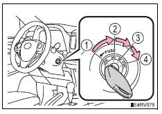
Changing the engine switch positions
- “Lock”
The steering wheel is locked and the key can be removed. (The key can be removed only when the shift lever is in p.)
- “Acc”
Some electrical components such as the audio system can be used.
- “On”
All electrical components can be used.
- “Start”
For starting the engine.
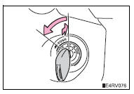
Turning the key from “acc” to “lock”
- Shift the shift lever to p.
- Push in the key and turn it to the
“lock” position.
If the engine does not start
The engine immobilizer system may not have been deactivated. („_P. 76) Contact your toyota dealer.
When the steering lock cannot be released
When starting the engine, the engine
switch may seem stuck in the “lock”
position. To free it, turn the key while turning
the steering wheel slightly left and
right. 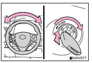
Key reminder function
A buzzer sounds if the driver’s door is opened while the engine switch is in the “lock” or “acc” position to remind you to remove the key.
Caution
When starting the engine
Always start the engine while sitting in the driver’s seat. Do not depress the accelerator pedal while starting the engine under any circumstances.
Doing so may cause an accident resulting in death or serious injury.
Caution when driving
Do not turn the engine switch to the “lock” position while driving. If, in an emergency, you must turn the engine off while the vehicle is moving, turn the engine switch only to the “acc” position to stop the engine. An accident may result if the engine is stopped while driving.
Notice
To prevent battery discharge
Do not leave the engine switch in the “acc” or “on” position for long periods of time without the engine running.
When starting the engine
- Do not crank the engine for more than 30 seconds at a time. This may overheat the starter and wiring system.
- Do not race a cold engine.
- If the engine becomes difficult to start or stalls frequently, have your vehicle checked by your toyota dealer immediately.

 Engine (ignition) switch
(vehicles with a
smart key system)
Engine (ignition) switch
(vehicles with a
smart key system)
Performing the following operations when carrying the electronic
key on your person starts the engine or changes engine
switch modes.
Starting the engine
Check that the parking brake is set.
...
Other materials:
Removal
Hint:
Use the same procedures for the rh side and lh side.
The procedures listed below are for the lh side.
Caution:
Be sure to read the precautionary notices concerning the
srs airbag system before servicing it (see page rs-1).
Disconnect cable from negative battery terminal
Cauti ...
Reassembly
Install generator rotor assembly
Install the washer onto the generator rectifier end
frame.
Install the generator rotor onto the generator
rectifier end frame.
Using a 32 mm socket wrench and press, slowly
push the generator drive end frame onto the
generator ...
Canister
Components
removal
Disconnect cable from negative battery
terminal
Caution:
Wait at least 90 seconds after disconnecting the
cable from the negative (-) battery terminal to
prevent airbag and seat belt pretensioner activation.
Remove canister
Disconnect the 2 tubes, hose a ...
