Toyota RAV4 (XA40) 2013-2018 Service Manual: Heated oxygen sensor
Components
Removal
- Disconnect cable from negative battery terminal
Caution:
Wait at least 90 seconds after disconnecting the cable from the negative (-) battery terminal to prevent airbag and seat belt pretensioner activation.
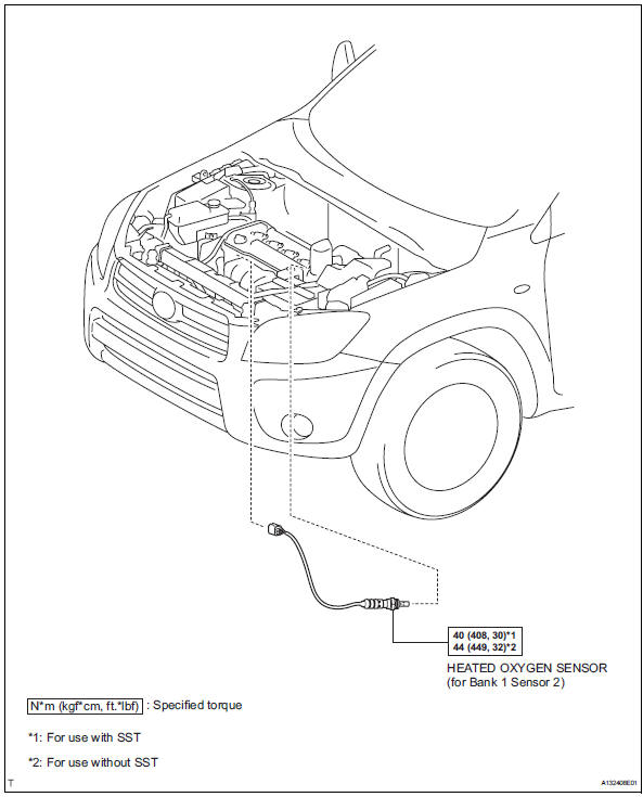
- Remove heated oxygen sensor (for bank 1 sensor 2)
- Disconnect the sensor connector.
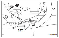
- Using sst, remove the sensor from the front exhaust pipe.
Sst 09224-00010
Inspection
- Inspect heated oxygen sensor (for bank 1 sensor 2)
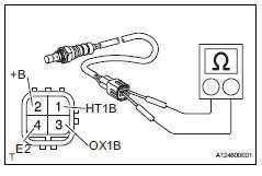
- Measure the resistance of the sensor.
Standard resistance 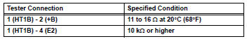
If the resistance is not as specified, replace the sensor.
Installation
- Install heated oxygen sensor (for bank 1 sensor 2)
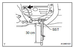
- Using sst, install the sensor to the front exhaust pipe.
Sst 09224-00010
Torque: 40 n*m (408 kgf*cm, 30 ft.*Lbf) for use with sst
44 N*m (449 kgf*cm, 32 ft.*Lbf) for use without sst
Hint:
- Use a torque wrench with a fulcrum length of 30 cm (11.81 In.).
- Make sure sst and wrench are connected in a straight line.
- Connect the sensor connector.
- Connect cable to negative battery terminal
- Check for exhaust gas leaks
 Air fuel ratio sensor
Components
On-vehicle inspection
Check air fuel ratio compensation system
Connect the intelligent tester to the dlc3.
Turn the ignition switch on.
Select the following menu item ...
 Fuel tank cap
Inspection
Inspect fuel tank cap assembly
Visually check that the cap and gasket are not
deformed or damaged.
If the result is not as specified, replace the cap
assembly or gaske ...
Other materials:
Windshield wipers and
washer
Operating the lever can
switch between automatic
operation and manual operation,
or can use the
washer.
NOTICE
â– When the windshield is dry
Do not use the wipers, as they
may damage the windshield.
Operating the wiper lever
Operating the lever operates
the wipers or washer as follows:
Intermittent ...
Removal
Caution:
Be sure to read the precautionary notices concerning the
srs airbag system before servicing it (see page rs-1).
Disconnect cable from negative battery
terminal
Caution:
Wait at least 90 seconds after disconnecting the
cable from the negative (-) battery terminal to
prevent air ...
Problem symptoms table (2006/01- )
Hint:
Use the table below to help determine the cause of the
problem symptom. The potential causes of the symptoms
are listed in order of probability in the "suspected area"
column of the table. Check each symptom by checking the
suspected areas in the order they are listed. Re ...
