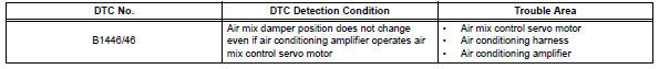
Toyota RAV4 (XA40) 2013-2018 Service Manual: Air mix damper control servo motor circuit (driver side)

Description
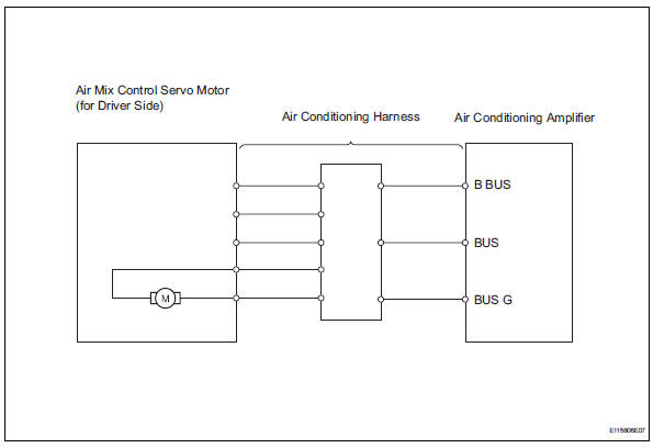
The air mix damper servo sends pulse signals to indicate the damper position to the air conditioning amplifier. The air conditioning amplifier activates the motor (normal or reverse) based on these signals to move the air mix damper (driver seat) to the appropriate position. This adjusts the amount of air passing through the heater core after passing the evaporator and controls the temperature of the blown air.
Hint:
Confirm that there are no mechanical problems because this dtc can be output when either a damper link or damper is mechanically locked.
Wiring diagram
Inspection procedure
- Read value of intelligent tester (air mix servo targ pulse (d))
- Connect the intelligent tester (with can vim) to the dlc3.
- Turn the ignition switch on and turn the intelligent tester main switch on.
- Select the items below in the data list, and read the value displayed on the intelligent tester.
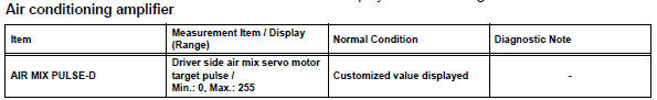
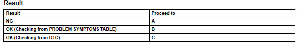
Ok: the display is as specified in the normal condition column.

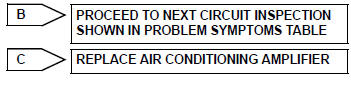
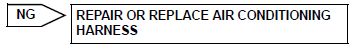
- Replace air mix control servo motor
Hint:
Since the servo motor cannot be tested when it is removed from the vehicle, replace the servo motor with a normal one and check that the condition returns to normal.
Ok: same problem does not occur.

System is ok
 Air outlet damper control servo motor circuit
Description
The damper servo sends pulse signals to indicate the damper position to the
air conditioning amplifier.
The air conditioning amplifier activates the motor (normal or reverse) bas ...
 Compressor solenoid circuit (2005/11-2006/01)
Description
In this circuit, the compressor receives a refrigerant compression demand
signal from the air conditioning
amplifier. Based on this signal, the compressor changes the degree of
r ...
Other materials:
General maintenance (2005/11-2006/01)
Inspect steering linkage and gear housing
Check the steering wheel free play.
Check the steering linkage for looseness or
damage.
Check that the tie rod ends do not have
excessive play
Check that the dust seals and boots are not
damaged.
Check that the boot clamps are not ...
Manual air conditioning system
Air conditioning controls
Fan speed control switch
Temperature control switch
On/off switch
Windshield defogger switch
Rear window and outside rear view mirror defoggers* switch
Airflow mode control switch
Outside/recirculated air mode switch
"A/C" switch
"MAX A/C" switch
*: If equipped
...
Compressor circuit
Description
When the a/c switch is turned on, the magnetic clutch on signal is sent from
the air conditioning
amplifier. Then the mg clt relay turns on to operate the magnetic clutch.
Wiring diagram
Inspection procedure
Perform active test by intelligent tester (a/c mag clutch)
C ...
