Toyota RAV4 (XA40) 2013-2018 Service Manual: Air outlet damper control servo motor circuit
![]()
Description
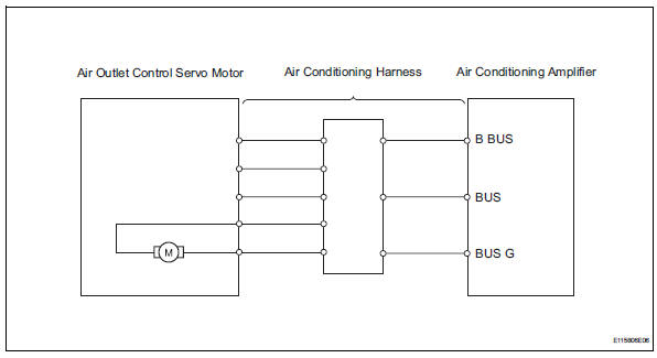
The damper servo sends pulse signals to indicate the damper position to the air conditioning amplifier.
The air conditioning amplifier activates the motor (normal or reverse) based on these signals to move the mode damper to the appropriate position, which controls the air outlet modes.
Hint:
Confirm that there are no mechanical problems because this dtc can be output when either a damper link or damper is mechanically locked.
Wiring diagram
Inspection procedure
- Read value of intelligent tester (air out pulse)
- Connect the intelligent tester (with can vim) to the dlc3.
- Turn the ignition switch on and turn the intelligent tester main switch on.
- Select the items below in the data list, and read the value displayed on the intelligent tester.
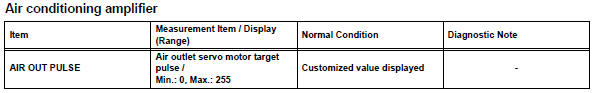
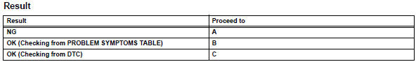
Ok: the display is as specified in the normal condition column.

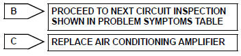
- Replace mode damper servo sub-assembly
hint:
Since the servo motor cannot be tested when it is removed from the vehicle, replace the servo motor with a normal one and check that the condition returns to normal.
Ok: same problem does not occur.

System is ok
 Air inlet damper control servo motor circuit
Description
The damper servo (air inlet control) sends pulse signals to indicate the
damper position to the air
conditioning amplifier. The air conditioning amplifier activates the motor
(no ...
 Air mix damper control servo motor circuit (driver
side)
Air mix damper control servo motor circuit (driver
side)
Description
The air mix damper servo sends pulse signals to indicate the damper position
to the air conditioning
amplifier. The air conditioning amplifier activates the motor (normal or
reve ...
Other materials:
Installation
Hint:
Use the same procedures for the lh side and rh side.
The procedures listed below are for the lh side.
A bolt without a torque specification is shown in the
standard bolt chart (see page ss-2).
Install front shoulder belt anchor adjuster assembly
Align the adjuster pos ...
How to proceed with troubleshooting (2005/11-2006/01)
Hint:
Use these procedures to troubleshoot the air conditioning
system.
*: Use the intelligent tester.
Vehicle brought to workshop
Customer problem analysis and symptom check
Inspect battery voltage
Standard voltage:
11 to 14 v
If the voltage is below 11 v, rechar ...
Valve clearance
Adjustment
Disconnect cable from negative battery
terminal
Caution:
Wait at least 90 seconds after disconnecting the
cable from the negative (-) battery terminal to
prevent airbag and seat belt pretensioner activation.
Remove front wheel rh
Remove no. 1 Engine under cover
Remove ...
