Toyota RAV4 (XA40) 2013-2018 Service Manual: Installation
- Install throttle body
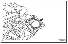
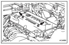
- Install a new gasket onto the intake manifold.
- Install the throttle body and fuel pipe clamp with the 4 bolts.
Torque: 30 n*m (305 kgf*cm, 22 ft.*Lbf)
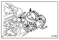
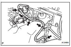
- Connect the fuel tube into the clamp.
- Connect the wire harness clamp.
- Connect the throttle position sensor and control motor connector.
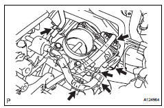
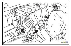
- Connect the no. 1 Throttle body hose to the throttle body
- Connect the no. 2 Water by-pass hose to the throttle body.
- Connect the water by-pass hose to the throttle body.
- Connect the purge line hose to the throttle body.
- Install air cleaner cap
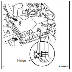
- Install the air cleaner filter element onto the air cleaner case.
- Insert the hinge part of the air cleaner cap into the air cleaner case, then hang the 2 hook clamps.
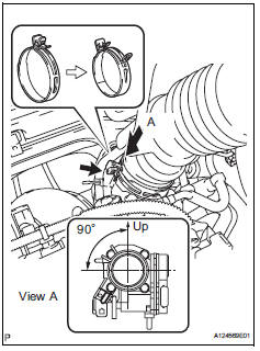
- Align the matchmarks of the no. 1 Air cleaner hose
and throttle body, and then connect the air cleaner
hose no. 1 To the throttle body and unfasten the no.
1 Air cleaner hose clamp.
Notice:
Make sure that the hose clamp is at the correct angle.
- Connect the purge line hose to the clamp.
- Connect the no. 2 Ventilation hose to the air cleaner hose.
- Install the 4 wire harness clamps.
- Connect the mass air flow meter connector.
- Connect cable to negative battery terminal
- Add engine coolant (see page co-6)
- Check for engine coolant leakage (see page co-1)
- Install no. 1 Engine cover
- Install the cover with the 2 nuts.
Torque: 7.0 N*m (71 kgf*cm, 62 in.*Lbf)
 Inspection
Inspect throttle body
Measure the resistance of the throttle control motor.
Standard resistance
If the result is not as specified, replace the throttle
body. ...
 Knock sensor
...
Other materials:
Problem symptoms table (2005/11-2006/01)
Hint:
Use the table below to help determine the cause of the
problem symptom. The potential causes of the symptoms
are listed in order of probability in the "suspected area"
column of the table. Check each symptom by checking the
suspected areas in the order they are listed. Re ...
How to proceed with troubleshooting
Notice:
Dtcs for the can communication system are as
follows: u0073, u0100, u0105, u0121, u0122, u0123,
u0124, u0126, u0129, c1280, c1296, c1297, and
b1499.
Refer to the troubleshooting procedures of each
system if dtcs regarding the can communication
system are not output.
Turn th ...
General maintenance (2006/01- )
Inspect steering linkage and gear housing
Check the steering wheel free play.
Check the steering linkage for looseness or
damage.
Check that the tie rod ends do not have
excessive play.
Check that the dust seals and boots are not
damaged.
Check that the boot clamps are not ...
