Toyota RAV4 (XA40) 2013-2018 Service Manual: Compressor solenoid circuit (2005/11-2006/01)

Description
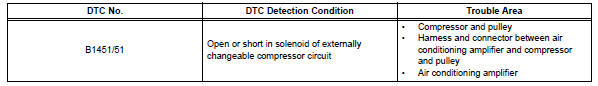
In this circuit, the compressor receives a refrigerant compression demand signal from the air conditioning amplifier. Based on this signal, the compressor changes the degree of refrigerant compression.
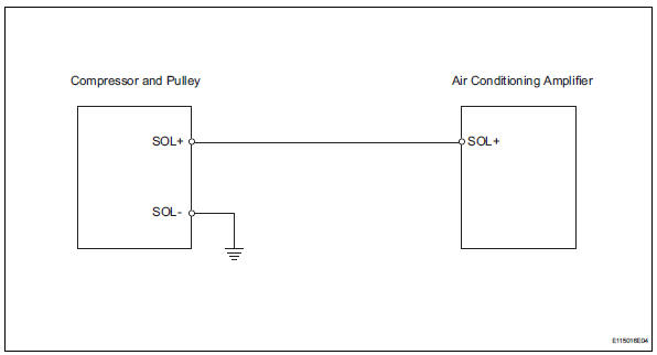
Wiring diagram
Inspection procedure
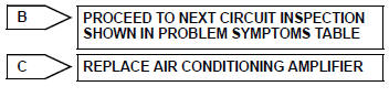
- Read value of intelligent tester (reg ctrl currnt)
- Connect the intelligent tester (with can vim) to the dlc3.
- Turn the ignition switch on and turn the intelligent tester main switch on.
- Select the items below in the data list, and read the value displayed on the intelligent tester.
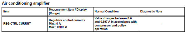
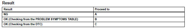
Ok: the display is as specified in the normal condition column.

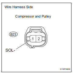
- Inspect compressor and pulley
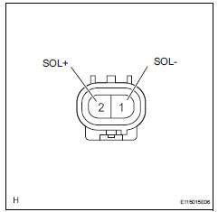
- Disconnect the compressor and pulley.
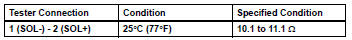
- Measure the resistance of the connector.
Standard resistance


- Check wire harness (compressor and pulley - air conditioning amplifier)
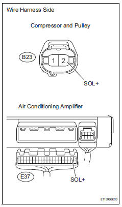
- Disconnect the b23 compressor and pulley connector.
- Disconnect the e37 amplifier connector.
- Measure the resistance of the wire harness side connectors.
Standard resistance
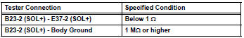

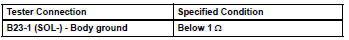
- Check wire harness (compressor and pulley - body ground)
- Disconnect the b23 compressor and pulley connector.
- Measure the resistance of the wire harness side connector.
Standard resistance

Replace air conditioning amplifier
 Air mix damper control servo motor circuit (driver
side)
Air mix damper control servo motor circuit (driver
side)
Description
The air mix damper servo sends pulse signals to indicate the damper position
to the air conditioning
amplifier. The air conditioning amplifier activates the motor (normal or
reve ...
 Compressor solenoid circuit (2006/01- )
Description
In this circuit, the compressor receives a refrigerant compression demand
signal from the air conditioning
amplifier. Based on this signal, the compressor changes the degree of
r ...
Other materials:
Evaporative emission system reference orifice
Dtc summary
Hint:
The reference orifice is located inside the canister pump module.
Description
The description can be found in the evap (evaporative emission) system (see
page es-335).
Inspection procedure
Refer to the evap system (see page es-340).
Monitor description
5 Hours* af ...
4Wd control ecu communication stop mode
Description
Hint:
For vehicle with 4wd only.
Wiring diagram
Inspection procedure
Notice:
Turn the ignition switch off before measuring the resistances of the
main wire and the branch
wire.
After the ignition switch is turned off, check that the key reminder
warning system ...
Only rear door lh lock / unlock functions do not operate
Description
The main body ecu receives lock / unlock switch signals and activates the
door lock motor accordingly.
Wiring diagram
Inspection procedure
Inspect rear door with motor lock assembly lh
Apply the battery voltage to the door lock motor and
check the operation of th ...
