Toyota RAV4 (XA40) 2013-2018 Service Manual: Disassembly (2005/11-2006/01)
- Remove front axle inboard joint boot no. 2 Clamp lh
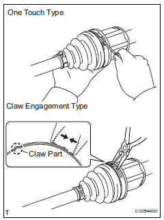
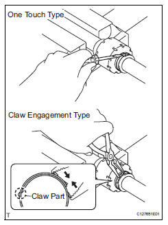
- One touch type:
- Using a screwdriver, remove the no. 2 Inboard joint boot clamp, as shown in the illustration.
- Claw engagement type:
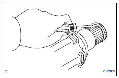
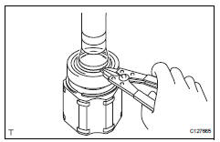
Using needle-nose pliers, remove the no. 2 Inboard joint boot clamp, as shown in the illustration.
- Remove front axle inboard joint boot no.
2 Clamp rh
Hint:
Using needle-nose pliers, remove the no. 2 Inboard joint boot clamp, as shown in the illustration.
- Remove front axle inboard joint boot clamp lh
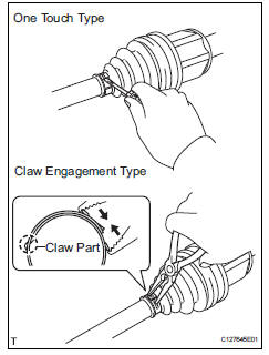
- One touch type:
- Using a screwdriver, remove the inboard joint boot clamp, as shown in the illustration.
- Claw engagement type:
Using needle-nose pliers, remove the inboard joint boot clamp, as shown in the illustration.
- Remove front axle inboard joint boot clamp rh
Hint:
Use the same procedures described for the lh side.
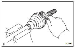
- Remove front axle inboard joint boot
- Remove the boot from the inboard joint.
- Remove front drive inboard joint assembly lh
- Remove any old grease from the inboard joint.
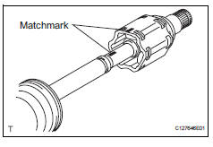
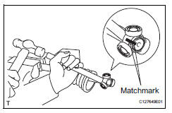
- Put matchmarks on the inboard joint and outboard joint shaft.
Notice:
Do not punch the marks.
- Remove the inboard joint from the outboard joint shaft.
- Using a snap ring expander, remove the shaft snap ring.
- Put matchmarks on the outboard joint shaft and tripod joint.
Notice:
Do not punch the marks.
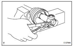
- Using a brass bar and hammer, tap out the tripod joint from the outboard joint shaft.
Notice:
Do not tap the rollers.
- Remove the inboard joint boot.
- Remove front drive shaft damper clamp lh
- One touch type:
- Using a screwdriver, remove the drive shaft damper clamp, as shown in the illustration.
- Claw engagement type:
- Using needle-nose pliers, remove the drive shaft damper clamp, as shown in the illustration.
- Remove front drive shaft damper lh
- Remove the front drive shaft damper.
- Remove front drive shaft damper clamp rh
Hint:
Use the same procedures described for the lh side.
- Remove front drive shaft damper rh
Hint:
Use the same procedures described for the lh side.
- Remove front axle outboard joint boot no. 2 Clamp lh
- Using a screwdriver, remove the no. 2 Outboard joint boot clamp, as shown in the illustration.
- Remove front axle outboard joint boot clamp lh
- Using a screwdriver, remove the outboard joint boot clamp, as shown in the illustration.
- Remove front axle outboard joint boot
- Remove the outboard joint boot from the outboard joint shaft.
- Remove any old grease from the outboard joint.
- Remove front drive shaft hole snap ring lh
- Using a screwdriver, remove the hole snap ring.
- Remove front drive shaft dust cover lh
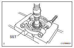
- Using sst and a press, press out the front drive shaft dust cover.
Sst 09950-00020
Notice:
Be careful not to drop the inboard joint
- Remove front drive shaft dust cover rh
- Using a press, press out the drive shaft dust cover.
- Remove front drive shaft bearing
- Using a snap ring expander, remove the drive shaft hole snap ring.
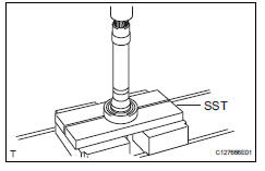
- Using sst and a press, press out the drive shaft bearing.
Sst 09527-10011
- Remove the snap ring.
 Removal
(2006/01- )
Removal
(2006/01- )
Remove front wheel
Drain automatic transaxle fluid
Drain the automatic transaxle fluid for u140f (see
page ax-147).
Drain the automatic transaxle fluid for u241e (see
page ax-146).
...
 Disassembly (2006/01- )
Remove front axle inboard joint boot no. 2
Clamp
One touch type:
using a screwdriver, remove the no. 2 Inboard joint
boot clamp, as shown in the illustration.
Claw engagement typ ...
Other materials:
Initializing the tire pressure
warning system (if
equipped)
â– The tire pressure warning
system must be initialized
in the following circumstances:
When rotating the tires.
When changing the tire.
After registering the ID codes.
When the tire pressure warning
system is initialized, the current
tire inflation pressure is set as
the benchmark pressure.
â ...
Torque converter clutch solenoid performance (shift solenoid valve dsl)
Description
The ecm uses the signals from the throttle position sensor, air-flow meter,
turbine (input) speed sensor,
intermediate (counter) shaft speed sensor and crankshaft position sensor to
monitor the engagement
condition of the lock-up clutch.
Then the ecm compares the engagement ...
Headlight aim
Vertical movement adjusting
bolts
Adjustment bolt A
Adjustment bolt B
Before checking the headlight
aim
Make sure the vehicle has a
full tank of gasoline and the
area around the headlight is
not deformed.
Park the vehicle on level
ground.
Make sure the tire inflation
pressure is at the ...
