Toyota RAV4 (XA40) 2013-2018 Service Manual: Disassembly (2006/01- )
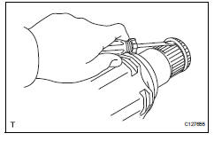
- Remove front axle inboard joint boot no. 2 Clamp
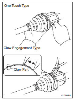
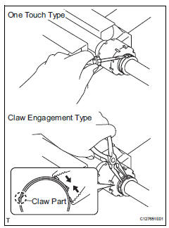
- One touch type: using a screwdriver, remove the no. 2 Inboard joint boot clamp, as shown in the illustration.
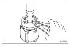
- Claw engagement type: using needle-nose pliers, remove the no. 2 Inboard joint boot clamp, as shown in the illustration.
- Remove front axle inboard joint boot clamp
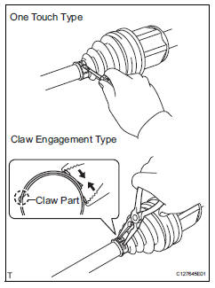
- One touch type: using a screwdriver, remove the inboard joint boot clamp, as shown in the illustration.
- Claw engagement type: using needle-nose pliers, remove the inboard joint boot clamp, as shown in the illustration.
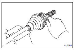
- Remove front axle inboard joint boot
- Remove the boot from the inboard joint.
- Remove front drive inboard joint assembly lh
- Remove any old grease from the inboard joint.
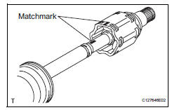
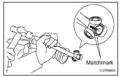
- Put matchmarks on the inboard joint and outboard joint shaft.
Notice:
Do not punch the marks.
- Remove the inboard joint from the outboard joint shaft.
- Using a snap ring expander, remove the shaft snap ring.
- Put matchmarks on the outboard joint shaft and tripod joint.
Notice:
Do not punch the marks.
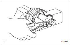
- Using a brass bar and hammer, tap out the tripod joint from the outboard joint shaft.
Notice:
Do not tap the rollers.
- Remove the inboard joint boot.
- Remove front drive shaft inboard joint assembly rh
Hint:
Use the same procedures described for the lh side.
- Remove front drive shaft damper clamp lh
- One touch type: using a screwdriver, remove the drive shaft damper clamp, as shown in the illustration.
- Claw engagement type: using needle-nose pliers, remove the drive shaft damper clamp, as shown in the illustration.
- Remove front drive shaft damper lh
- Remove the front drive shaft damper
- Remove front drive shaft damper clamp rh
Hint:
Use the same procedures described for the lh side.
- Remove front drive shaft damper rh
Hint:
Use the same procedures described for the lh side.
- Remove front axle outboard joint boot no. 2 Clamp
- Using a screwdriver, remove the no. 2 Outboard joint boot clamp, as shown in the illustration.
- Remove front axle outboard joint boot clamp
- Using a screwdriver, remove the outboard joint boot clamp, as shown in the illustration.
- Remove front axle outboard joint boot
- Remove the outboard joint boot from the outboard joint shaft.
- Remove any old grease from the outboard joint.
- Remove front drive shaft hole snap ring lh
- Using a screwdriver, remove the hole snap ring.
- Remove front drive shaft dust cover lh
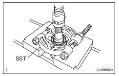
- Using sst and a press, press out the front drive shaft dust cover.
Sst 09950-00020
Notice:
Be careful not to drop the inboard joint.
- Remove front drive shaft dust cover rh
Hint:
Use the same procedures described for the lh side.
- Remove front drive shaft bearing (for rh)
- Using a snap ring expander, remove the drive shaft hole snap ring.

- Using sst and a press, press out the drive shaft bearing.
Sst 09527-10011
- Remove the bearing bracket snap ring.
 Disassembly (2005/11-2006/01)
Remove front axle inboard joint boot no. 2
Clamp lh
One touch type:
Using a screwdriver, remove the no. 2 Inboard
joint boot clamp, as shown in the illustration.
Claw eng ...
 Reassembly (2005/11-2006/01)
Install front drive shaft bearing
Using sst and a press, press in the drive shaft
bearing to the inboard joint rh.
Sst 09527-10011, 09710-04081
Notice:
The bearing should be instal ...
Other materials:
Light bulbs
You may replace the following bulbs by yourself. The difficulty
level of replacement varies depending on the bulb. If necessary
bulb replacement seems difficult to perform, contact your
toyota dealer.
For more information about replacing other light bulbs, contact
your toyota dealer.
Prepari ...
Transmission fluid temperature sensor "A" circuit
Description
The automatic transmission fluid (atf) temperature sensor converts the atf
temperature into a
resistance value which is input into the ecm.
The ecm applies a voltage to the temperature sensor through ecm terminal tho1.
The sensor resistance changes with the atf temperature. ...
Front passenger occupant classification system
Your vehicle is equipped with a front passenger occupant
classification system. This system detects the conditions of
the front passenger seat and activates or deactivates the
front passenger airbag and seat cushion airbag in the front
passenger side.
System components
SRS warning light
Driver's ...
