Toyota RAV4 (XA40) 2013-2018 Service Manual: Fog light assembly
Components
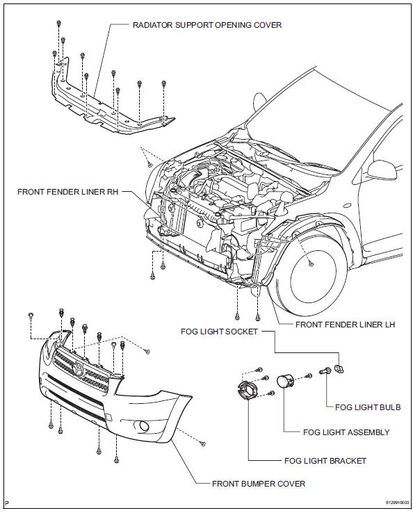
Removal
Hint:
- Use the same procedures for the rh and lh sides.
- The procedures listed below are for the lh side.
- Disconnect cable from negative battery terminal
Caution:
Wait at least 90 seconds after disconnecting the cable from the negative (-) battery terminal to prevent airbag and seat belt pretensioner activation.
- Remove front fender liner lh (see page et-6)
- Remove front fender liner rh (see page et-4)
- Remove radiator support opening cover (see page et-4)
- Remove front bumper cover (see page et-5)
- Remove fog light assembly
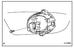
- Disconnect the connector.
- Remove the bolt and fog light.
Disassembly
Hint:
- Use the same procedures for the rh side and lh sides.
- The procedures listed below are for the lh side.
- Remove fog light bulb
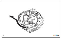
- Turn the bulb in the direction indicated by the arrow and pull to remove it.
Adjustment
- Vehicle preparation for fog light aim adjustment
- Prepare the vehicle:
- Ensure that the vehicle has no damage or deformation around the fog lights.
- Fill up the fuel tank.
- Make sure that all of the different types of oil in the vehicle (engine oil, etc.) Are filled to the specified levels.
- Make sure that the coolant is filled to the specified level.
- Inflate the tires to the appropriate pressure.
- Place the spare tire, tools, and jack in their original positions.
- Unload the vehicle.
- Have a person that weighs approximately 55 kg (121 lb) sit in the driver seat.
- Preparation for fog light aiming (using screen)
- Prepare the vehicle according to the following conditions:
- Move the vehicle to a location that is sufficiently dark so that the fog light cutoff line can be visually checked. The cutoff line is an imaginary plane below which fog light light is projected and above which light is not projected.
- Move the vehicle to a level surface.
- Point the front of the vehicle at a wall. The wall must be perpendicular to the surface that the vehicle is on.
- Position the vehicle 10 m (32.8 Ft.) From the wall.
- Push down on the vehicle several times to settle the suspension.
Hint:
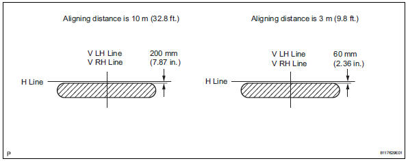
A distance of 10 m (32.8 Ft.) Between the vehicle and the wall is necessary for proper aim adjustment. If unavailable, secure a distance of exactly 3 m (9.8 Ft.). In the illustrations below, view the part of the illustration applicable to the distance from the vehicle to the wall.
Notice:
Be careful not to damage the suspension.
- Prepare a piece of thick white paper that is approximately 2 m (6.6 Ft.) (Height) x 4 m (13.1 Ft.) (Width) to use as a screen.
- Draw a vertical line down the center of the screen (v line).
- Set the screen as shown in the illustration.
Hint:
- Stand the screen perpendicular to the ground.
- Align the v line on the screen with the center of the vehicle.
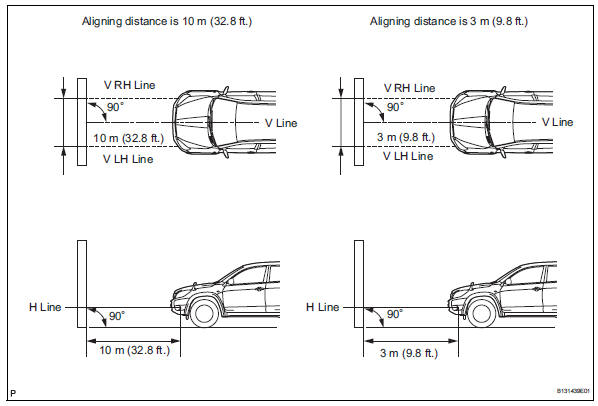
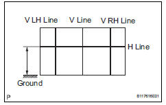
- Draw base lines (h line, v lh and v rh lines) on the screen as shown in the illustration.
H line (fog light height): draw a horizontal line across the screen so that it passes through the center marks. The h line should be at the same height as the bulb center marks of the fog lights.
V lh line, v rh line (center mark position of lh and rh fog lights): draw 2 vertical lines so that they intersect the h line at each center mark.
- Inspect fog light aiming
- Choose a fog light to inspect first. Cover or disconnect the connector of the other fog light to prevent light from that fog light from affecting the fog light aiming inspection.
- Start the engine.
Notice:
Engine rpm must be 1,500 or more.
- Turn on the fog lights and make sure that the cutoff line is within the specified area shown in the illustration.
- Adjust fog light aiming
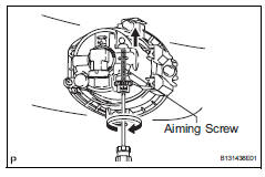
- Adjust the fog light aim into the specified range by turning the aiming screw with a screwdriver.
Notice:
If the screw is tightened too much, loosen it and then retighten it so that the final turn of the screw is in the clockwise direction.
 Headlight assembly
Components
Removal
Hint:
Use the same procedures for the rh and lh sides.
The procedures listed below are for the lh side.
Disconnect cable from negative battery
terminal
Rem ...
 Rear combination light assembly
Components
Removal
Hint:
Use the same procedures for the rh and lh sides.
The procedures listed below are for the lh side.
Disconnect cable from negative battery
terminal
Cautio ...
Other materials:
Luggage compartment features
Cargo hooks
Raise the hook to use.
The cargo hooks are provided for
securing loose items.
WARNING
â– When cargo hooks are not in
use
To avoid injury, always return the
hooks to their stowed positions
when not in use.
Deck board
â– Flipping the deck board
upside down
The deck board can be flipped
...
Evaporator temperatur sensor
Removal
Remove air conditioning unit
Remove the air conditioning radiator (see page ac-
185).
Remove evaporator temperature sensor
(see page ac-193)
Inspection
Inspect evaporator temperature sensor
Measure the resistance of the sensor.
Standard resistance
No ...
Front stabilizer bar
Components
Removal
Remove front wheel
Remove front stabilizer link assembly lh
Remove the 2 nuts and stabilizer link.
Remove front stabilizer link assembly rh
Hint:
Use the same procedures described for the lh side.
Remove front suspension member brace front lh
...
