Toyota RAV4 (XA40) 2013-2018 Service Manual: Removal (2006/01- )
- Remove front wheel
- Drain automatic transaxle fluid
- Drain the automatic transaxle fluid for u140f (see page ax-147).
- Drain the automatic transaxle fluid for u241e (see page ax-146).
- Drain the automatic transaxle fluid for u151f (see page ax-173).
- Remove front axle hub nut (see page ah-8)
- Disconnect front speed sensor lh (see page bc-191)
- Disconnect front speed sensor rh
Hint:
Use the same procedures described for the lh side.
- Disconnect front disc brake cylinder assembly lh (see page br-40)
- Disconnect front disc brake cylinder assembly rh
Hint:
Use the same procedures described for the lh side.
- Disconnect front stabilizer link assembly lh (see page sp-30)
- Disconnect front stabilizer link assembly rh
- Disconnect front suspension lower no. 1 Arm sub-assembly lh (see page sp-22)
- Disconnect front suspension lower no. 1 Arm sub-assembly rh
Hint:
Use the same procedures described for the lh side.
- Disconnect steering knuckle with axle hub lh
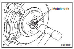
- Put matchmarks on the drive shaft and axle hub.
Notice:
Do not punch the marks.
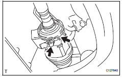
- Using a plastic-faced hammer, disconnect the steering knuckle with axle hub.
Notice:
Be careful not to damage the boot and speed sensor rotor.
Do not excessively push out the drive shaft from the axle assembly.
- Disconnect steering knuckle with axle hub rh
Hint:
Use the same procedures described for the lh side.
- Disconnect tie rod end sub-assembly lh (see page ps-42)
- Disconnect tie rod end sub-assembly rh
Hint:
Use the same procedures described for the lh side.
- Remove front drive shaft assembly lh
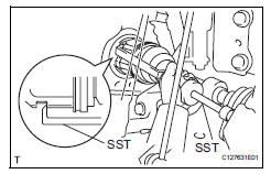
- Using sst, remove the front drive shaft.
Sst 09520-01010, 09520-24010 (09520-32040)
Notice:
- Be careful not to damage the transaxle case oil seal, inboard joint boot and drive shaft dust cover.
- Be careful not to drop the drive shaft.
- Remove front drive shaft assembly rh
- Squeeze the ends of the snap ring, and remove the snap ring from the bearing bracket.
- Remove the bearing bracket bolt and remove the front drive shaft from the bearing bracket.
Notice:
- Do not damage the oil seal.
- Do not damage the boot.
- Do not allow the drive shaft to fall off.
Hint:
If the connection is stiff, use a brass bar and hammer to lightly tap the edge of the inboard joint rh and remove it.
- Fix front axle assembly
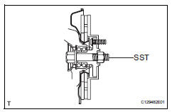
Notice:
The hub bearing could be damaged if it is subjected to the vehicle weight, such as when moving the vehicle with the drive shaft removed. Therefore, if it is absolutely necessary to place the vehicle weight on the hub bearing, first support it with sst.
Sst 09608-16042 (09608-02021, 09608-02041)
 Removal
(2005/11-2006/01)
Removal
(2005/11-2006/01)
Remove front wheel
Drain automatic transaxle fluid
Drain the automatic transaxle fluid for u140f (see
page ax-147).
Drain the automatic transaxle fluid for u241e (see
page ax-146).
...
 Disassembly (2005/11-2006/01)
Remove front axle inboard joint boot no. 2
Clamp lh
One touch type:
Using a screwdriver, remove the no. 2 Inboard
joint boot clamp, as shown in the illustration.
Claw eng ...
Other materials:
Opening the fuel tank cap
Pull up the opener to open the
fuel filler door.
Turn the fuel tank cap slowly to
open.
Hang the fuel tank cap on the
back of the fuel filler door.
...
Short to b+ in can bus line
Description
There may be a short circuit between the can bus line and +b when there is
resistance between
terminals 6 (canh) and 16 (bat) or terminals 14 (canl) and 16 (bat) of the dlc3.
Wiring diagram
Inspection procedure
Notice:
Turn the ignition switch off before measuring ...
For vehicles equipped with mobile communication systems
Install the antenna as far away from the ecu and
sensors of the vehicle electronic systems as
possible.
Install an antenna feeder at least 20 cm (7.87 In.)
Away from the ecu and sensors of the vehicle
electronic systems. For details about ecu and
sensor locations, refer to the sec ...
