
Toyota RAV4 (XA50) 2019-2026 Owners Manual: Air conditioning filter
The air conditioning filter must be changed regularly to maintain air conditioning efficiency.
Removal method
1. Turn the engine switch to OFF.
2. Open the glove box and slide off the damper.
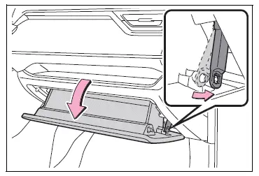
3. Push in each side of the glove box to disconnect the claws, and then slowly and fully open the glove box while supporting it.
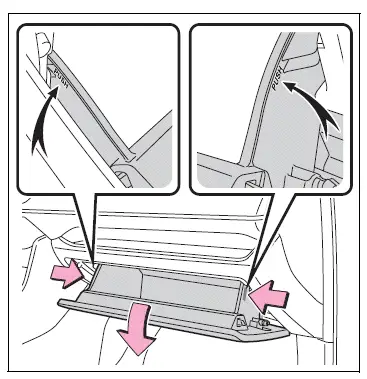
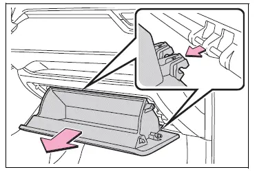
4. With the glove box fully open, slightly lift up the glove box and pull toward the seat to detach the bottom of the glove box.
Do not use excessive force if the glove box does not detach when lightly pulled. Instead, pull toward the seat while slightly adjusting the height of the glove box.
5. Unlock the filter cover (A), pull the filter cover out of the claws (B), and remove the filter cover.
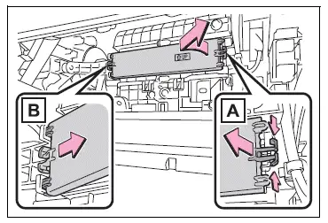
6. Remove the filter case.
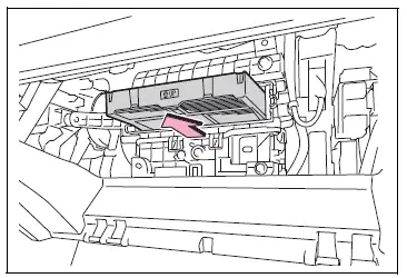
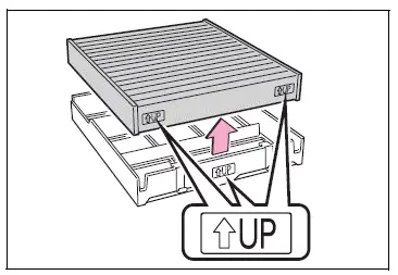
7. Remove the air conditioning filter from the filter case and replace it with a new one.
The " UP" marks shown on the
filter should be pointing up.
8. When installing, reverse the steps listed.
â– Checking interval
Inspect and replace the air conditioning filter according to the maintenance schedule. In dusty areas or areas with heavy traffic flow, early replacement may be required. (For scheduled maintenance information, please refer to the "Owner's Manual Supplement" or "Scheduled Maintenance".)
â– If air flow from the vents decreases dramatically
The filter may be clogged. Check the filter and replace if necessary.
NOTICE
â– When using the air conditioning system
Make sure that a filter is always installed.
Using the air conditioning system without a filter may cause damage to the system.
â– When removing the glove box
Always follow the specified procedure to remove the glove box. If the glove box is removed without following the specified procedure, the hinge of the glove box may become damaged.
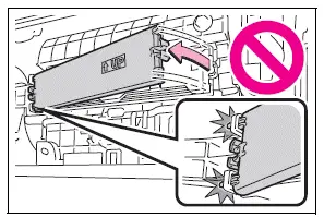
â– To prevent damage to the filter cover
When moving the filter cover in the direction of arrow to release the fitting, pay attention not to apply excessive force to the claws. Otherwise, the claws may be damaged.
 Wheels
If a wheel is bent, cracked or
heavily corroded, it should
be replaced. Otherwise, the
tire may separate from the
wheel or cause a loss of
handling control.
Wheel selection
When replacing wheels, care ...
 Wiper insert replacement
When replacing the wiper
insert, perform the following
procedure to operate each
wiper.
Windshield wipers
â– Windshield wiper blade
removal and installation
1. While holding the hook portion A
of the ...
Other materials:
Can bus line
Description
When any dtc for the can communication system is output, first measure the
resistance between the
terminals of the dlc3 to specify the trouble area, and check that there is not a
short in the can main wire,
between the main wire, to +b, or to gnd.
Wiring diagram
Inspecti ...
Evaporative emission control system pressure sensor
Dtc summary
Hint:
The canister pressure sensor is built into the canister pump module.
Description
The description can be found in the evap (evaporative emission) system (see
page es-335).
Monitor description
Dtc p0450: canister pressure sensor abnormal fluctuation
If t ...
Disposal
Hint:
When scrapping a vehicle equipped with an srs or disposing
of the steering pad, be sure to deploy the airbag first in
accordance with the procedure described below. If any
abnormality occurs with the airbag deployment, contact the
service dept. Of toyota motor sales, u.S.A., Inc.
Caution ...
