Toyota RAV4 (XA40) 2013-2018 Service Manual: Abs warning light remains on
Description
If any of the following conditions are detected, the abs warning light remains on:
- The ecu connectors are disconnected from the skid control ecu.
- There is a malfunction in the skid control ecu internal circuit.
- There is an open or short in the wire harness between the combination meter and the skid control ecu.
Hint:
The intelligent tester may not be used when there is a malfunction in the skid control ecu.
Wiring diagram
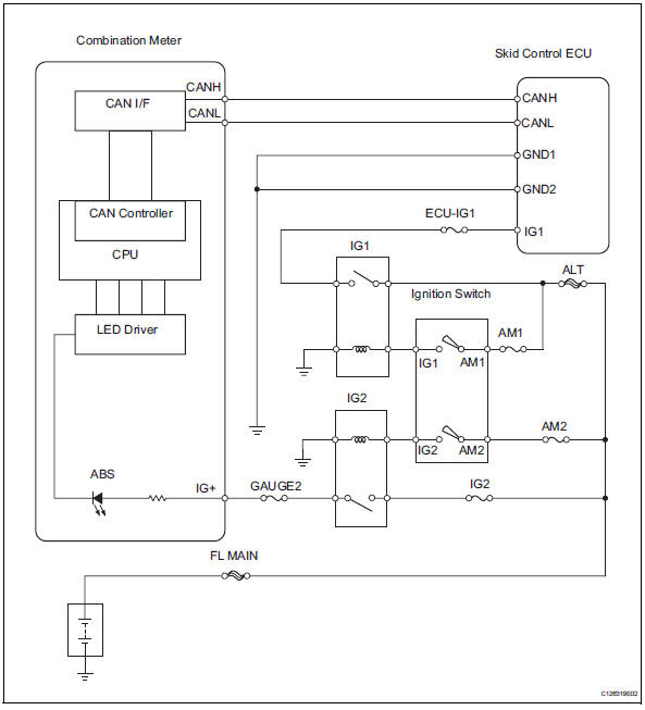
Inspection procedure
- Check can communication system
- Check if the can communication system dtc is output (see page ca-34).
Result 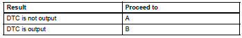

- Inspect skid control ecu connector
- Check if the skid control ecu connector is properly installed.
Ok: the skid control ecu connector is properly installed.

- Check wire harness (skid control ecu - battery and body ground)
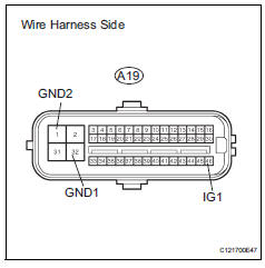
- Disconnect the a19 ecu connector.
- Measure the resistance of the wire harness side connector.
Standard resistance 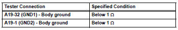
- Measure the voltage of the wire harness side connector.
Standard voltage 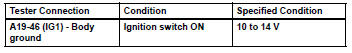

- Perform active test by intelligent tester (abs warning light)
- Select the active test, generate a control command, and then check that the abs warning light operates.

Ok: the abs warning light is turned on or off.
Hint:
When the abs warning light remains illuminated, opens in the wire harness of the combination meters or abnormalities in the meter circuit should be considered.

Replace abs and traction actuator assembly
 Control module communication bus off
Description
Inspection procedure
The skid control ecu inputs the signals from the ecm, steering angle sensor,
and yaw rate and
acceleration sensor via can communication system.
Ch ...
 Abs warning light does not come on
Wiring diagram
Refer to the abs warning light circuit (see page bc-135).
Inspection procedure
Check can communication system
Check if the can communication system dtc is output
(see page ...
Other materials:
Taillight relay circuit
Description
When the light control switch, located on the headlight dimmer switch, is
turned to the tail position, the
taillight relay (marking: t-lp) turns on to illuminate the front side marker
lights, rear taillights, side marker
lights and license plate light.
Wiring diagram
Ins ...
Warning lights and indicators
The warning lights and indicators on the instrument cluster and
center panel inform the driver of the status of the vehicle’s various
systems.
For the purpose of explanation, the following illustration displays
all warning lights and indicators illuminated.
Instrument cluster
Some indi ...
Seat belts
Make sure that all occupants
are wearing their seat
belts before driving the
vehicle.
WARNING
Observe the following precautions
to reduce the risk of injury in the
event of sudden braking, sudden
swerving or an accident.
Failure to do so may cause death
or serious injury.
â– Wearing a seat belt
E ...
