
Toyota RAV4 (XA40) 2013-2018 Service Manual: Terminals of ecu
- Check combination meter assembly
- Disconnect the e19 meter connector.
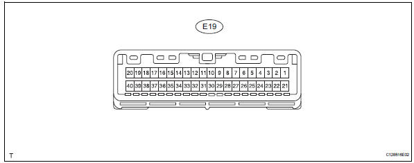
- Measure the voltage and resistance of the wire harness side connector.
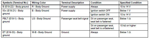
If the result is not as specified, there may be a malfunction on the wire harness side.
- Check heater control panel (for automatic air conditioning system)
- Disconnect the e23 panel connector.

- Measure the voltage and resistance of the wire harness side connector.
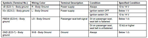
If the result is not as specified, there may be a malfunction on the wire harness side.
- Check clock assembly (for manual air conditioning system)

- Disconnect the e22 clock connector.
- Measure the voltage and resistance of the wire harness side connector.
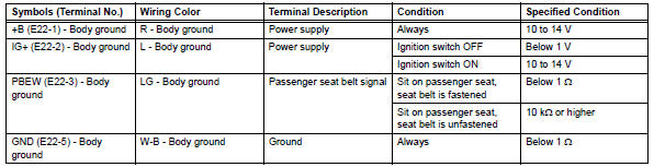
If the result is not as specified, there may be a malfunction on the wire harness side.
 Problem symptoms table
Hint:
Use the table below to help determine the cause of the
problem symptom. The potential causes of the symptoms are
listed in order of probability in the "suspected area" column
of th ...
 Diagnosis system
Description
Data of the system can be read through the data
link connector 3 (dlc3) of the vehicle.
Therefore, when the system seems to be
malfunctioning, use the intelligent tester t ...
Other materials:
Blower unit
Components
Removal
Disconnect cable from negative battery
terminal
Caution:
Wait at least 90 seconds after disconnecting the
cable from the negative (-) battery terminal to
prevent airbag and seat belt pretensioner activation.
Remove upper instrument panel
Remove the upper ...
How to proceed with troubleshooting (2005/11-2006/01)
Hint:
Use these procedures to troubleshoot the air conditioning
system.
*: Use the intelligent tester.
Vehicle brought to workshop
Customer problem analysis and symptom check
Inspect battery voltage
Standard voltage:
11 to 14 v
If the voltage is below 11 v, recha ...
Short in front passenger side squib 2nd step circuit
Description
The front passenger side squib 2nd step circuit consists of the center airbag
sensor and the front
passenger airbag.
The circuit instructs the srs to deploy when the deployment conditions are met.
These dtcs are recorded when a malfunction is detected in the front passenger ...
