
Toyota RAV4 (XA40) 2013-2018 Service Manual: Problem symptoms table
Hint:
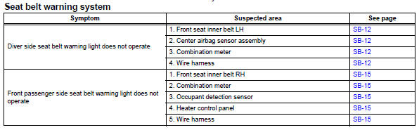
Use the table below to help determine the cause of the problem symptom. The potential causes of the symptoms are listed in order of probability in the "suspected area" column of the table. Check each symptom by checking the suspected areas in the order they are listed. Replace parts as necessary.
 Operation check
Inspect driver side seat belt warning light
Turn the ignition switch on.
When the driver seat belt is not fastened, check that
the driver seat belt warning light on the combination
mete ...
 Terminals of ecu
Check combination meter assembly
Disconnect the e19 meter connector.
Measure the voltage and resistance of the wire
harness side connector.
If the result is not as specifie ...
Other materials:
Problem symptoms table
Hint:
Use the table below to help determine the cause of the
problem symptom. The potential causes of the symptoms
are listed in order of probability in the "suspected area"
column of the table. Check each symptom by checking the
suspected areas in the order they are listed. Re ...
Lost communication with front satellite sensor bus rh
Description
The front airbag sensor rh consists of the diagnostic circuit and the frontal
deceleration sensor.
If the center airbag sensor receives signals from the frontal deceleration
sensor, it determines whether or
not the srs should be activated.
Dtc b1602/83, b1603/83, b1612/83 ...
Steering wheel
Adjustment procedure
The steering wheel can be adjusted to a comfortable position.
Hold the steering wheel and
press the lever down.
Adjust to the ideal position by
moving the steering wheel horizontally
and vertically.
After adjustment, pull the lever up
to secure the steering ...
