Toyota RAV4 (XA40) 2013-2018 Service Manual: Front airbag sensor rh circuit malfunction
![]()
Description
The front airbag sensor rh consists of the diagnostic circuit, the frontal deceleration sensor, etc.
If the center airbag sensor assembly receives signals from the frontal deceleration sensor, it determines whether or not the srs should be activated.
Dtc b1610/13 is recorded when a malfunction is detected in the front airbag sensor rh circuit.

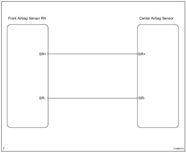
Wiring diagram
Inspection procedure
- Check front airbag sensor rh
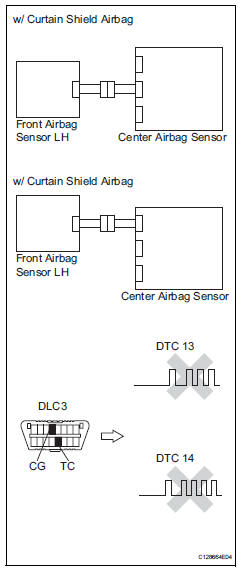
- Turn the ignition switch off.
- Disconnect the cable from the negative (-) battery terminal, and wait for at least 90 seconds.
- Interchange the front airbag sensor rh and lh, and connect the connectors to them.
- Connect the cable to the negative (-) battery terminal, and wait for at least 2 seconds.
- Turn the ignition switch on, and wait for at least 60 seconds.
- Clear the dtcs (see page rs-49).
- Turn the ignition switch off.
- Turn the ignition switch on, and wait for at least 60 seconds.
- Check the dtcs (see page rs-49).
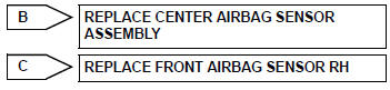
Result 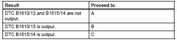
Hint:
Dtcs other than dtc b1610/13 and b1615/14 may be output at this time, but they are not related to this check.

Use simulation method to check
 Lost communication with front satellite sensor bus lh
Description
The front airbag sensor lh consists of the diagnostic circuit and the frontal
deceleration sensor.
If the center airbag sensor receives signals from the frontal deceleration
se ...
 Front airbag sensor lh circuit malfunction
Description
The front airbag sensor lh consists of the diagnostic circuit, the frontal
deceleration sensor, etc.
If the center airbag sensor receives signals from the frontal deceleration
sens ...
Other materials:
Refueling
Opening the fuel tank cap
Perform the following steps
to open the fuel tank cap:
Before refueling the vehicle
Close all the doors and windows,
and turn the engine
switch to OFF.
Confirm the type of fuel.
â– Fuel tank opening for unleaded
gasoline
To help prevent incorrect fueling,
your vehicle ...
Removal
Remove radiator grille sub-assembly
Remove the 4 bolts and 4 nuts.
Detach the 6 claws and remove the radiator grille.
Remove no. 1 Radiator grille lower
Detach the 16 claws and remove the radiator grille.
Remove no. 2 Radiator grille lower
Detac ...
Removal
(2005/11-2006/01)
Remove front wheel
Drain automatic transaxle fluid
Drain the automatic transaxle fluid for u140f (see
page ax-147).
Drain the automatic transaxle fluid for u241e (see
page ax-146).
Remove front axle hub nut (see page ah-6)
Disconnect front speed sensor lh (see page
bc-191) ...
