Toyota RAV4 (XA40) 2013-2018 Service Manual: Illumination circuit
Description
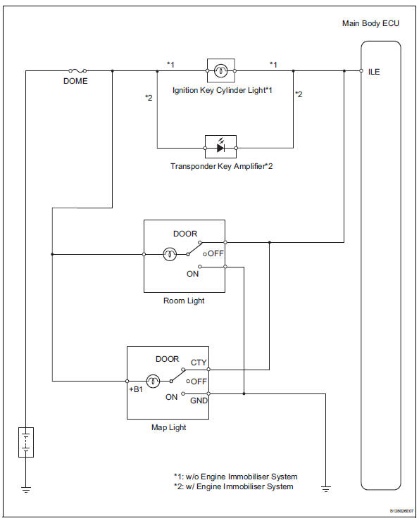
The main body ecu receives information regarding the door courtesy switch and door lock position switch, and turns on the room light.
Wiring diagram
Inspection procedure
- Perform active test by intelligent tester (main body ecu)
- Connect the intelligent tester (with can vim) to the dlc3.
- Turn the ignition switch to the on position and press the intelligent tester main switch on.
- Select the items below in the active test and then check the main body ecu operation.
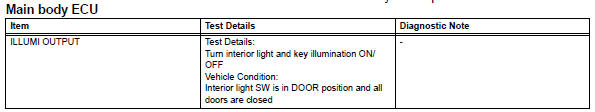
Ok: light comes on.

- Inspect fuse (dome)
- Remove the dome fuse from the engine room no. 2 Relay block.
- Measure the resistance of the fuse.
Standard resistance:
below 1 

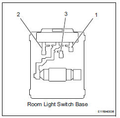
- Inspect room light assembly
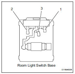
- Remove the room light assembly
- Measure the resistance of the room light switch base.
Standard resistance 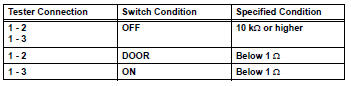


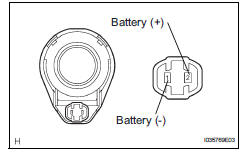
- Inspect room light bulb
- Remove the room light assembly.
- Connect the positive (+) lead from the battery to terminal 1 and the negative (-) lead to terminal 2, then check that the light comes on when the switch is in the door position.
Ok: light comes on.
- Connect the positive (+) lead from the battery to terminal 1 and the negative (-) lead to terminal 3, then check that the light comes on when the switch is in the on position.
Ok: light comes on.

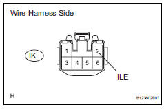
- Check harness and connector (battery - room light and main body ecu)
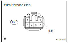
- Disconnect the ik instrument panel junction block connector.
- Measure the voltage of the wire harness side connector.
Standard voltage 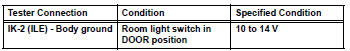

- Inspect map light bulb
- Remove the map light assembly.
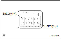
- Connect the positive (+) lead from the battery to terminal 6 and the negative (-) lead to terminal 1, then check that the light comes on when the switch is in the door position.
Ok: light comes on.
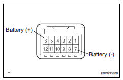
- Connect the positive (+) lead from the battery to terminal 6 and the negative (-) lead to terminal 7, then check that the light comes on when the switch is in the on position.
Ok: light comes on.


- Inspect map light
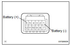
- Replace the map light bulb with a normally functioning one or a new one.
- Connect the positive (+) lead from the battery to terminal 6 and the negative (-) lead to terminal 1, then check that the light comes on when the switch is in the door position.
Ok: light comes on.
- Connect the positive (+) lead from the battery to terminal 6 and the negative (-) lead to terminal 7, then check that the light comes on when the switch is in the on position.
Ok: light comes on.

Replace map light bulb
- Check wire harness (battery - map light and main body ecu)
- Disconnect the ik instrument panel junction block connector.
- Measure the voltage of the wire harness side connector.
Standard voltage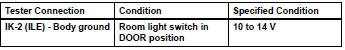

- Inspect ignition key cylinder light
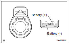
- W/ engine immobiliser system
- Remove the transponder key amplifier (ignition key cylinder light).
- Connect the positive (+) lead from the battery to terminal 2 and the negative (-) lead to terminal 6, then check that the light comes on.
Ok: light comes on.
- W/o engine immobiliser system
- Remove the ignition key cylinder light.
- Connect the positive (+) lead from the battery to terminal 2 and the negative (-) lead to terminal 1, then check that the light comes on.
Ok: light comes on.

- Check wire harness (battery - main body ecu)
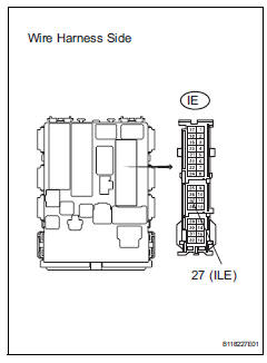
- Disconnect the ie instrument panel junction block connector.
- Measure the voltage of the wire harness side connector.
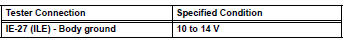

Replace instrument panel junction block
 Footwell light circuit
Description
The main body ecu receives information regarding the door lock position
switch and ignition switch, and
turns on each foot light.
Wiring diagram
Inspection procedure
Perform ...
 Taillight relay circuit
Description
When the light control switch, located on the headlight dimmer switch, is
turned to the tail position, the
taillight relay (marking: t-lp) turns on to illuminate the front side marker ...
Other materials:
Luggage compartment
features
Cargo hooks
Raise the hooks to use.
The cargo hooks are provided for
securing loose items.
Caution
When the cargo hooks are not in use
To avoid injury, always return the cargo hooks to their stowed
positions.
Grocery bag hooks
Notice
Grocery bag hook weight capacity
Do not hang ...
SRS airbags
The SRS airbags inflate when the vehicle is subjected to certain
types of severe impacts that may cause significant injury
to the occupants. They work together with the seat belts to
help reduce the risk of death or serious injury.
SRS airbag system
â– Location of the SRS airbags
SRS front airbags ...
Suspension & axle front shock absorber with coil spring (for sport package)
Components
Removal
Hint:
Use the same procedures for the rh side and lh side.
The procedures listed below are for the lh side.
Remove front wheel
Remove front speed sensor lh (see page bc-
191)
Remove front stabilizer link assembly lh
(see page sp-30)
Remove front shock a ...
