Toyota RAV4 (XA40) 2013-2018 Service Manual: Taillight relay circuit
Description
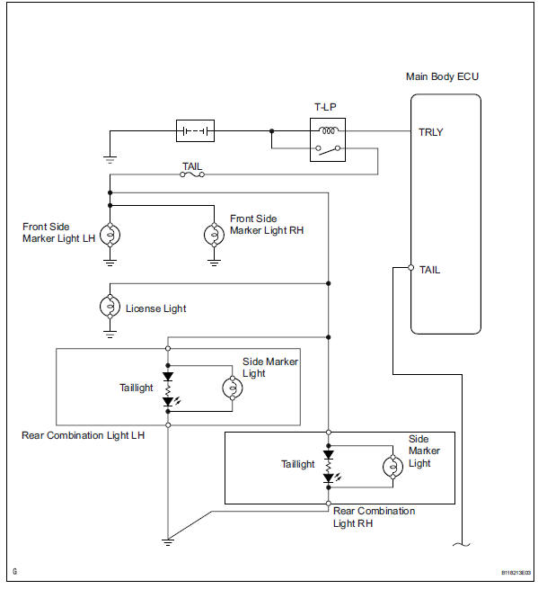
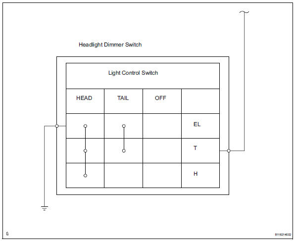
When the light control switch, located on the headlight dimmer switch, is turned to the tail position, the taillight relay (marking: t-lp) turns on to illuminate the front side marker lights, rear taillights, side marker lights and license plate light.
Wiring diagram
Inspection procedure
- Check whether lights illuminate
- Check whether the following lights illuminate: front side marker lights, rear taillights, side marker lights and license plate light.


- Inspect fuse (tail)
- Remove the tail fuse from the instrument panel junction block.
- Measure the resistance of the fuse.
Standard resistance:
below 1 

- Check wire harness (battery - instrument panel junction block)
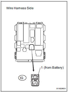
- Disconnect the ig instrument panel junction block connector.
- Measure the voltage of the wire harness side connector.
Standard voltage 

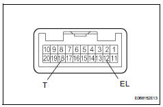
- Check wire harness (main body ecu - headlight dimmer switch)
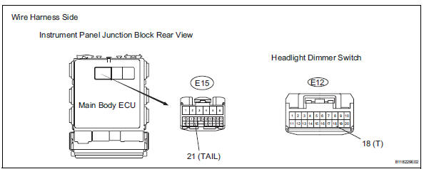
- Disconnect the e15 main body ecu connector.
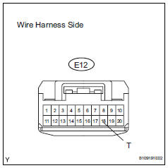
- Disconnect the e12 headlight dimmer switch connector.
- Measure the resistance of the wire harness side connectors.
Standard resistance 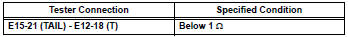

- Check wire harness (battery - headlight dimmer switch)
- Connect the e15 main body ecu connector.
- Disconnect the e12 headlight dimmer switch connector.
- Measure the voltage of the wire harness side connector.
Standard voltage 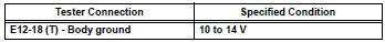

- Check wire harness (headlight dimmer switch - body ground)
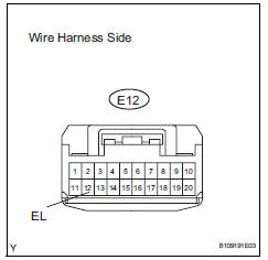
- Disconnect the e12 headlight dimmer switch connector.
- Measure the resistance of the wire harness side connector.
Standard resistance 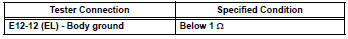

- Inspect headlight dimmer switch
- Remove the headlight dimmer switch.
- Measure the resistance of the switch.
Standard resistance 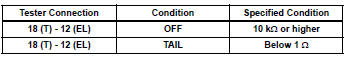

Replace instrument panel junction block
- Check instrument panel junction block (taillight relay)
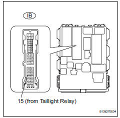
- Disconnect the ib instrument panel junction block connector.
- Measure the voltage of the junction block.
Standard voltage 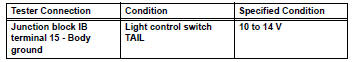

- Check wire harness (taillight relay - front side marker light and body ground)
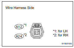
- Disconnect the a12 and a24 front side marker light connectors.
- Measure the voltage and resistance of the wire harness side connectors.
Standard resistance 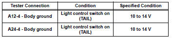
standard resistance 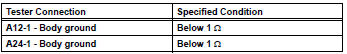

Replace bulb
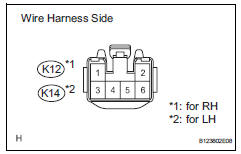
- Check wire harness (main body ecu - rear combination light)
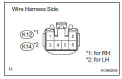
- Disconnect the k12 and k14 rear combination light connectors.
- Measure the voltage and resistance of the wire harness side connectors.
Standard voltage 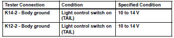
Standard resistance 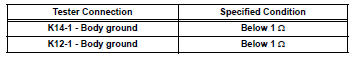

Replace rear combination light
- Check wire harness (main body ecu - license plate light and body ground)
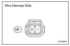
- Disconnect the q6 license plate light connector.
- Measure the voltage and resistance of the wire harness side connector.
Standard voltage 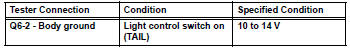
Standard resistance 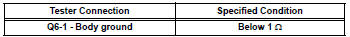

Replace bulb
- Check wire harness (main body ecu - rear combination light)
- Disconnect the k12 and k14 rear combination light connectors.
- Measure the voltage and resistance of the wire harness side connectors.
Standard voltage 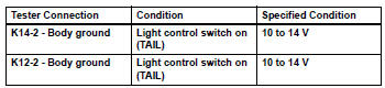
Standard resistance 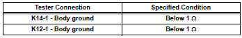

Replace bulb
 Illumination circuit
Description
The main body ecu receives information regarding the door courtesy switch and
door lock position
switch, and turns on the room light.
Wiring diagram
Inspection procedure
Perf ...
 Headlight assembly
Components
Removal
Hint:
Use the same procedures for the rh and lh sides.
The procedures listed below are for the lh side.
Disconnect cable from negative battery
terminal
Rem ...
Other materials:
Exhaust pipe
Installation
Install front exhaust pipe assembly
Using a vernier caliper, measure the free length of
the compression spring.
Minimum length:
41.5 Mm (1.634 In.)
If the length is less than the minimum, replace the
compression spring.
Install a new gasket by hand so that its ...
Inspection
Inspect camshaft timing oil control valve
assembly
Measure the resistance of the oil control valve.
Standard resistance
If the result is not as specified, replace the oil control
valve assembly.
Check the operation.
Apply battery voltage across the terminals and
chec ...
AHB (Automatic High
Beam)
The Automatic High Beam
uses an in-vehicle front
camera to assess the brightness
of streetlights, the
lights of vehicles ahead etc.,
and automatically turns the
high beams on or off as necessary.
WARNING
â– Limitations of the Automatic
High Beam
Do not overly rely on the Automatic
High Beam. Always ...
