
Toyota RAV4 (XA40) 2013-2018 Service Manual: How to proceed with troubleshooting (2006/01- )
Hint:
- Use these procedures to troubleshoot the air conditioning system.
- *: Use the intelligent tester.
- Vehicle brought to workshop

- Customer problem analysis and symptom check

- Inspect battery voltage
Standard voltage: 11 to 14 v
If the voltage is below 11 v, recharge or replace the battery before proceeding.

- Check can communication system*
- Use the intelligent tester to check if the can communication system is functioning.
Result 


- Check dtc or check sensor check code through panel diagnosis*
- Check dtcs or sensor check codes.
- Write down the dtcs or sensor check codes.
- Clear the dtcs or sensor check codes.
- Check whether the dtcs or sensor check codes recur.
- Reproduce the problem symptoms in accordance with the dtcs or sensor check codes that were written down, and check whether the dtcs or sensor check codes recur.
Hint:
Refer to the dtc chart when any dtcs or sensor check codes are output.
Result 


- Refer to problem symptoms table
Result 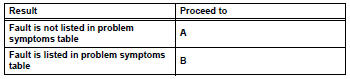


- Overall analysis and troubleshooting*
- Data list / active test (see page ac-37)
- Panel diagnosis (indicator check) (see page ac-31)
- Panel diagnosis (sensor check) (see page ac-31)
- Panel diagnosis (actuator check) (see page ac-31)
- Terminals of ecu (see page ac-27)

- Adjust, repair or replace

- Confirmation test

End
 How to proceed with troubleshooting (2005/11-2006/01)
Hint:
Use these procedures to troubleshoot the air conditioning
system.
*: Use the intelligent tester.
Vehicle brought to workshop
Customer problem analysis and symptom check
...
 Customize parameters
Hint:
The following items can be customized.
Notice:
When the customer requests a change in a function,
first make sure that the function can be customized.
Be sure to make a note of the cur ...
Other materials:
Freeze frame data
Description
Freeze frame data records the engine conditions (fuel
system, calculated load, engine coolant temperature,
fuel trim, engine speed, vehicle speed, etc.) When a
malfunction is detected. When troubleshooting, it can
help determine if the vehicle was running or stopped, the
engin ...
Parking Support Brake function
(static objects)
If the sensors detect a static object, such as a wall, in the
traveling direction of the vehicle and the system determines
that a collision may occur due to the vehicle suddenly moving
forward due to an accidental accelerator pedal operation, the
vehicle moving the unintended direction due to the wr ...
Front seat concentrated
airflow mode (S-FLOW)
This function automatically controls
the air conditioning airflow
so that priority is given to the
front seats. Unnecessary air
conditioning is suppressed, contributing
to increased fuel efficiency.
Front seat concentrated airflow
mode operates in the following
situations.
No passengers are detec ...
