Toyota RAV4 (XA40) 2013-2018 Service Manual: Lost communication with front satellite sensor bus lh
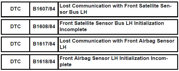
Description
The front airbag sensor lh consists of the diagnostic circuit and the frontal deceleration sensor.
If the center airbag sensor receives signals from the frontal deceleration sensor, it determines whether or not the srs should be activated.
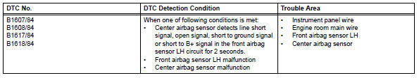
Dtc b1607/84, b1608/84, b1617/84 or b1618/84 is recorded when a malfunction is detected in the front airbag sensor lh circuit.
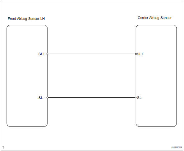
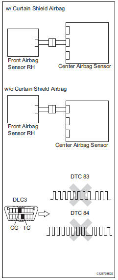
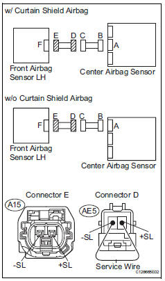
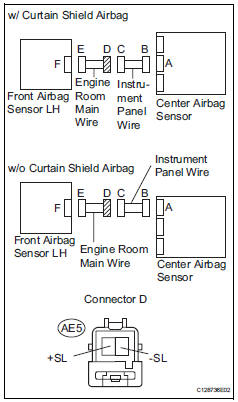
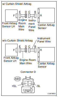
Wiring diagram
Inspection procedure
- Check connection of connector
- Turn the ignition switch off.
- Disconnect the cable from the negative (-) terminal, and wait for at least 90 seconds.
- Check that the connectors are properly connected to the center airbag sensor and the front airbag sensor lh.
Ok: the connectors are properly connected.

- Check front airbag sensor lh circuit (open)
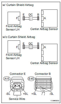
- Disconnect the connectors from the center airbag sensor and the front airbag sensor lh.
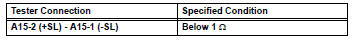
- Using a service wire, connect a15-2 (+sl) and a15-1 (- sl) of connector e.
Notice:
Do not forcibly insert a service wire into the terminals of the connector when connecting.
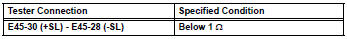
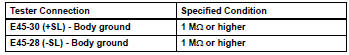
- Measure the resistance of the wire harness side connector.
Standard resistance


- Check front airbag sensor lh circuit (short)
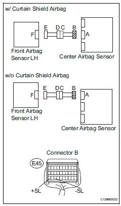
- Disconnect the service wire from connector e.
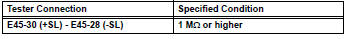
- Measure the resistance of the wire harness side connector.
Standard resistance

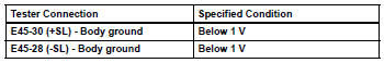
- Check front airbag sensor lh circuit (to b+)
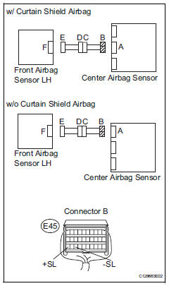
- Connect the cable to the negative (-) battery terminal, and wait for at least 2 seconds.
- Turn the ignition switch on.
- Measure the voltage of the wire harness side connectors.
Standard voltage


- Check front airbag sensor lh circuit (to ground)
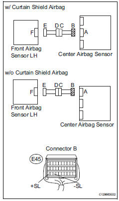
- Turn the ignition switch off.
- Disconnect the cable from the negative (-) battery terminal, and wait for at least 90 seconds.
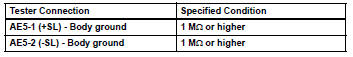
- Measure the resistance of the wire harness side connector.
Standard resistance


- Check front airbag sensor lh
- Connect the connectors to the center airbag sensor.
- Interchange the front airbag sensor rh and lh, and connect the connectors to them.
- Connect the cable to the negative (-) battery terminal, and wait for at least 2 seconds.
- Turn the ignition switch on, and wait for at least 60 seconds.
- Clear the dtcs (see page rs-49).
- Turn the ignition switch off
- Turn the ignition switch on, and wait for at least 60 seconds.
- Check the dtcs (see page rs-49).
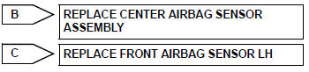
Result 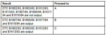
Hint:
Dtcs other than b1602/83, b1603/83, b1612/83, b1613/83, b1607/84, b1608/84, b1617/84 and b1618/ 84 may be output at this time, but they are not related to this check.

Use simulation method to check
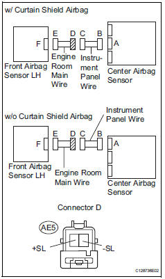
- Check engine room main wire (open)
- Disconnect the service wire from connector e.
- Disconnect the engine room main wire connector from the instrument panel wire.
- Using a service wire, connect ae5-1 (+sl) and ae5-2 (- sl) of connector d.
Notice:
Do not forcibly insert a service wire into the terminals of the connector when connecting.
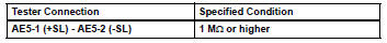
- Measure the resistance of the wire harness side connector.
Standard resistance

Repair or replace instrument panel wire
- Check engine room main wire (short)
- Disconnect the engine room main wire connector from the instrument panel wire.
- Measure the resistance of the wire harness side connector.
Standard resistance

Repair or replace instrument panel wire
- Check engine room main wire (to b+)
- Turn the ignition switch off.
- Disconnect the cable from the negative (-) battery terminal, and wait for at least 90 seconds.
- Disconnect the engine room main wire connector from the instrument panel wire.
- Connect the cable to the negative (-) battery terminal, and wait for at least 2 seconds.
- Turn the ignition switch on.
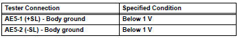
- Measure the voltage of the wire harness side connector
Standard voltage

Repair or replace instrument panel wire
- Check engine room main wire (to ground)
- Disconnect the engine room main wire connector from the instrument panel wire.
- Measure the resistance of the wire harness side connector.
Standard resistance

Repair or replace instrument panel wire
 Lost communication with front satellite sensor bus rh
Description
The front airbag sensor rh consists of the diagnostic circuit and the frontal
deceleration sensor.
If the center airbag sensor receives signals from the frontal deceleration
se ...
 Front airbag sensor rh circuit malfunction
Description
The front airbag sensor rh consists of the diagnostic circuit, the frontal
deceleration sensor, etc.
If the center airbag sensor assembly receives signals from the frontal
dece ...
Other materials:
Definition of terms
Terms
Definition
Monitor description
Description of what ecm monitors and how detects malfunctions
(monitoring purpose and
details).
Related dtcs
Group of diagnostic trouble codes that are output by ecm based on
same malfunction
detection logic.
...
Unlocking and locking the doors
Front doors
Grip the driver’s door handle to
unlock the door. Grip the passenger’s
door handle to unlock all the
doors.*
Make sure to touch the sensor on
the back of the handle.
The doors cannot be unlocked for
3 seconds after the doors are
locked.
*: The door unlock settings can be ...
Brake switch "A" / "B" correlation
Description
The stop light switch is a duplex system that transmits two signals: stp and
st1-. These two signals are
used by the ecm to monitor whether or not the brake system is working properly.
If the signals, which
indicate the brake pedal is being depressed and released, are detected ...
