Toyota RAV4 (XA40) 2013-2018 Service Manual: Air conditioning control assembly (for manual air conditioning system)
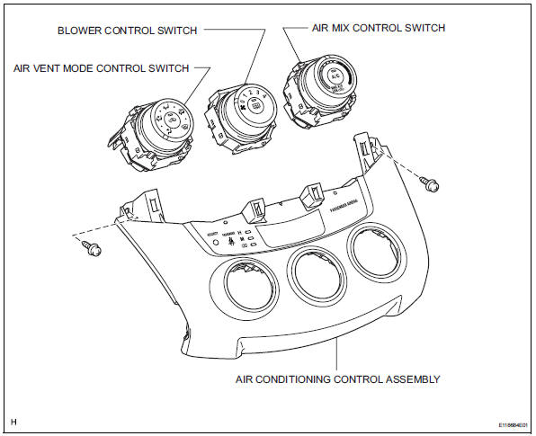
Components
Removal
- Disconnect cable from negative battery terminal
Notice:
Wait at least 90 seconds after disconnecting the cable from the negative (-) battery terminal to prevent airbag and seat belt pretensioner activation.
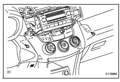
- Remove no. 2 Instrument cluster finish panel center (see page ip-5)
- Remove no. 1 Instrument cluster finish panel center (see page ip-5)
- Remove radio receiver assembly (see page ip-5)
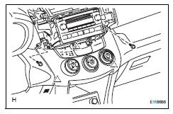
- Remove air conditioning control assembly
- Remove the 2 screws.
- Using a screwdriver, detach the 3 clips.
Hint:
Tape the screwdriver tip before use.
- Disconnect the connectors and remove the air conditioning control.
- Remove air mix control switch
- Detach the 2 claws and remove the air mix control switch.
- Remove blower control switch
- Detach the 2 claws and remove the blower control switch.
- Remove air vent mode control switch
- Detach the 2 claws and remove the mode control switch.
Installation
- Install air vent mode control switch
- Attach the 2 claws to install the mode control switch.
- Install blower control switch
- Attach the 2 claws to install the blower control switch.
- Install air mix control switch
- Attach the 2 claws to install the air mix control switch.
- Install air conditioning control assembly
- Connect the connectors.
- Attach the 3 clips to install the air conditioning control.
- Install the 2 screws.
- Install radio receiver assembly (w/ radio receiver) (see page ip-10)
- Install no. 1 Instrument cluster finish panel center (see page ip-10)
- Install no. 2 Instrument cluster finish panel center (see page ip-10)
- Connect cable to negative battery terminal
- Check srs warning light
- Check the srs warning light (see page rs-37).
 Air conditioning control assembly (for automatic air conditioning system)
Components
Removal
Disconnect cable from negative battery
terminal
Notice:
Wait at least 90 seconds after disconnecting the
cable from the negative (-) battery terminal to
prevent air ...
 Lighting
...
Other materials:
Brake pedal load sensing switch
Description
The brake pedal load sensing switch is turned on when the brake pedal is
depressed with force exceeding
a predetermined level.
The skid control ecu detects if the brake pedal is depressed or not via this
circuit.
Wiring diagram
Inspection procedure
Notice:
When repla ...
System description
Brief description
The can (controller area network) is a serial data
communication system for real time application. It is
a vehicle multiplex communication system which
has a high communication speed (500 kbps) and
the ability to detect malfunctions.
By pairing the canh and canl ...
Evaporative emission system switching valve control
Dtc summary
Hint:
The vent valve is built into the canister pump module.
Description
The description can be found in the evap (evaporative emission) system (see
page es-335).
Inspection procedure
Refer to the evap system (see page es-340).
Monitor description
5 Hours* after the ign ...
