Toyota RAV4 (XA40) 2013-2018 Service Manual: Air conditioning control assembly (for automatic air conditioning system)
Components
Removal
- Disconnect cable from negative battery terminal
Notice:
Wait at least 90 seconds after disconnecting the cable from the negative (-) battery terminal to prevent airbag and seat belt pretensioner activation.
- Remove no. 2 Instrument cluster finish panel center (see page ip-5)
- Remove no. 1 Instrument cluster finish panel center (see page ip-5)
- Remove radio receiver (see page ip-5)
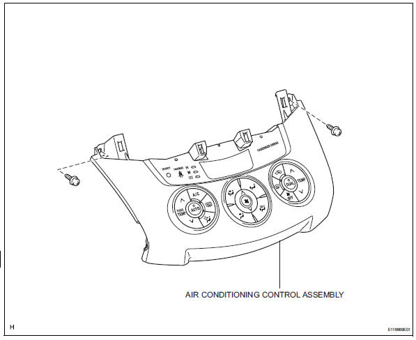
- Remove air conditioning control assembly
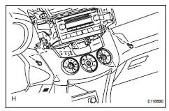
- Remove the 2 screws.
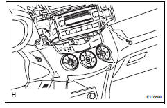
- Using a screwdriver, detach the 3 clips.
Hint:
Tape the screwdriver tip before use.
- Connect the connectors and remove the air conditioning control.
Installation
- Install air conditioning control assembly
- Install air conditioning control assembly
- Connect the connectors.
- Attach the 3 clips to install the air conditioning control.
- Install the 2 screws.
- Install radio receiver (see page ip-10)
- Install no. 1 Instrument cluster finish panel center (see page ip-10)
- Install no. 2 Instrument cluster finish panel center (see page ip-10)
- Connect cable to negative battery terminal
- Check srs warning light
- Check the srs warning light (see page rs-37).
 Heater relay
On-vehicle inspection
Inspect relay (marking: htr)
Measure the resistance of the htr relay.
Standard resistance
If the result is not as specified, replace the relay. ...
 Air conditioning control assembly (for manual air conditioning system)
Components
Removal
Disconnect cable from negative battery
terminal
Notice:
Wait at least 90 seconds after disconnecting the
cable from the negative (-) battery terminal to
prevent air ...
Other materials:
Steering angle sensor zero point malfunction
Description
The skid control ecu learns the steering sensor zero point every time the
ignition switch is turned on and
the vehicle is driven at 35 km/h (22 mph) or more for approximately 5 seconds.
The ecu also stores the
previous zero point.
If front wheel alignment or the steering wh ...
Rear no. 2 Suspension arm
Components
Removal
Hint:
Use the same procedures for the rh side and lh side.
The procedures listed below are for the lh side.
Remove rear wheel
Disconnect no. 2 Parking brake cable
assembly (see page pb-8)
Disconnect skid control sensor wire (for
2wd) (see page bc-198)
D ...
Inside rear view mirror
The rear view mirror's position
can be adjusted to
enable sufficient confirmation
of the rear view.
Adjusting the height of
rear view mirror
The height of the rear view mirror
can be adjusted to suit your
driving posture.
Adjust the height of the rear
view mirror by moving it up and
down.
WARNING
...
